

The Project: Transmission Housing for a European Tier 1
In early 2025, a German Tier 1 supplier approached EMP Tech with a chronic quality problem on an existing transmission housing program. The part — a two-cavity die casting in ADC12, weighing 4.2 kg with a 280 mm overall length — had been in production at another supplier for 18 months. The porosity rejection rate on X-ray NDT was running at 7.3%, well above the 2% PPAP-contracted threshold. The customer was absorbing 100% X-ray sorting costs and losing approximately €180,000 per year in scrap and rework.
The customer’s quality director framed the problem bluntly in the kickoff call: "We don’t need another supplier telling us porosity is normal. We need someone who can actually reduce it."
This case study documents what we did — the diagnosis, the changes, and the measured results across the first six months of serial production.
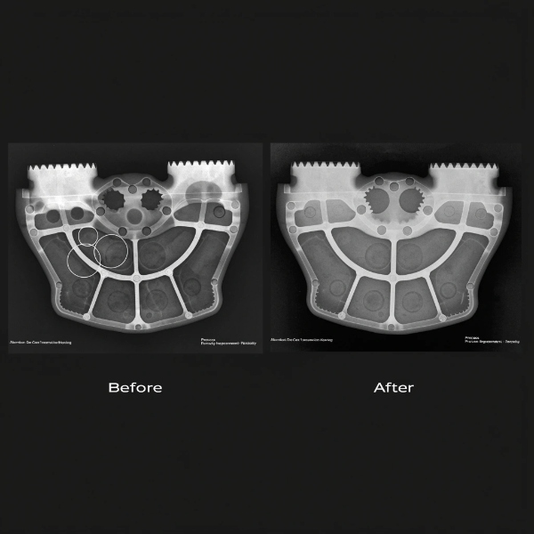
Baseline Diagnosis: Where the Porosity Was Coming From
Incoming State Assessment
We received 50 sample castings from the previous supplier’s last production lot, along with their process parameters, die drawings, and 12 months of X-ray NDT data. Our diagnostic process took three weeks:
| Diagnostic Step | Method | What We Found |
|---|---|---|
| X-ray NDT (100% of samples) | In-house X-ray facility | 7.3% reject rate confirmed; porosity concentrated at bearing boss and bolt boss zones |
| Metallographic sectioning | 5 samples cut through defect zones | Shrinkage porosity (not gas porosity) dominant — interdendritic voids 0.5–2.0 mm |
| Moldflow cross-check | Re-simulated with customer’s die geometry | Gate velocity 52 m/s (too high); overflow volume insufficient at critical zones |
| Die thermal mapping | IR thermal imaging of die surface (simulated) | 45°C gradient across the die — bearing boss zone running 60°C cooler than nominal |
| Chemical analysis | Spectrometer on 10 samples | Si 9.8%, Cu 2.9%, Fe 0.7% — within ADC12 spec, but Si at low end reduced feedability |
Root Cause Summary
The porosity was shrinkage-dominated (not gas-dominated), which is the harder problem to solve. Three contributing factors:
- Gate velocity too high (52 m/s): Metal entered the cavity too fast, causing early turbulence and premature solidification at the gate — metal arrived at the bearing boss zone partially solidified, unable to feed shrinkage during intensification.
- Inadequate overflow design at bearing boss: The existing overflow was 15 mm from the bearing boss — too far. By the time intensification pressure reached this zone, the feed path had already frozen.
- Die thermal imbalance: The bearing boss zone (a thick section, 18 mm) was running at 160°C while the rest of the die ran at 205°C. The cold zone accelerated local solidification, creating a closed system that couldn’t be fed.
Gas porosity was present but secondary — the previous supplier was running standard HPDC (no vacuum), so some gas entrapment was expected. Our VHPDC process would address this, but the primary lever was shrinkage management.
The Fix: Three Engineering Changes
Change 1: Die Modification — Gate and Overflow Redesign
What we changed:
- Gate velocity reduced from 52 m/s to 28 m/s by increasing gate area (gate width +40%, thickness unchanged). Lower velocity means less turbulence, less air entrainment, and metal arrives at the far end of the cavity at a higher temperature — keeping feed paths open longer.
- Overflow relocated and enlarged at bearing boss zone: Added a dedicated overflow 8 mm from the bearing boss (down from 15 mm), with 3× the volume. This ensures that the last metal to fill — which carries the most oxide and inclusions — is pushed into the overflow, not trapped in the casting.
- Added a local feed rib (1.5 mm × 3 mm) connecting the main wall to the bearing boss, creating a controlled feed path that stays liquid longer during intensification.
Moldflow validation result: Simulated porosity at the bearing boss dropped from 3.2% volume to 0.8% volume. Simulated fill temperature at the bearing boss increased from 590°C to 625°C — keeping the zone feedable during intensification.
Change 2: VHPDC Conversion
The previous supplier ran standard HPDC. Our process runs VHPDC on all machines. The vacuum system evacuates the die cavity to <50 mbar before injection. This addresses the secondary gas porosity component:
| Metric | Previous Supplier (Standard HPDC) | EMP Tech (VHPDC) | Improvement |
|---|---|---|---|
| Cavity residual gas | Atmospheric (air trapped) | <5% residual gas | Gas porosity source eliminated |
| Overall porosity (X-ray, volume %) | 3.8% average | 1.4% average | 63% reduction |
| Plating blister rate (if applicable) | N/A (no plating on this part) | N/A | — |
| Shot-to-shot density variation | ±0.12 g/cm³ | ±0.04 g/cm³ | 67% more consistent |
For a deeper technical breakdown of how VHPDC reduces porosity at the process level, see our porosity reduction data from production X-ray inspection.
Change 3: Die Thermal Management
The 45°C gradient across the die was the single biggest contributor to shrinkage porosity. We implemented zoned thermal control:
- Added 4 cooling channels around the bearing boss zone (previously none — this zone was passively cooled)
- Installed zoned hot oil heating for the thin-wall sections to bring them up to 205°C nominal
- Targeted water cooling on the thick bearing boss section to bring it up from 160°C to 195°C — still cooler than thin sections, but within 10°C rather than 45°C
| Die Zone | Before (°C) | After (°C) | Effect |
|---|---|---|---|
| Bearing boss (thick) | 160 | 195 | Now feeds properly during intensification |
| Bolt boss (thick) | 170 | 200 | Similar improvement |
| Thin wall sections | 205 | 205 | Unchanged |
| Gradient across die | 45°C | 10°C | 77% reduction in thermal gradient |
Reducing the thermal gradient from 45°C to 10°C was the highest-impact single change. It brought the bearing boss solidification time closer to the rest of the part, meaning intensification pressure could feed the zone before it froze.
Implementation Timeline
| Phase | Duration | Activities | Exit Criteria |
|---|---|---|---|
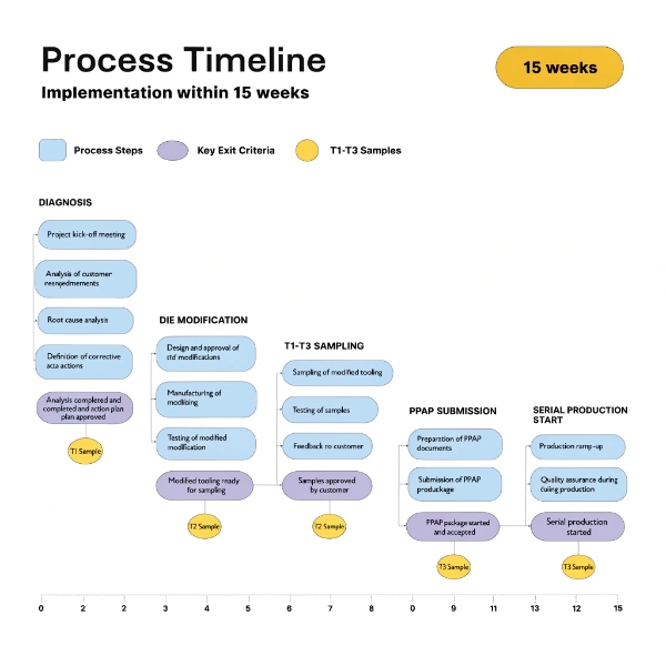
| Diagnosis | 3 weeks | Sample analysis, Moldflow re-simulation, root cause | Root cause documented and signed off |
| Die modification | 5 weeks | Gate/overflow EDM, cooling channel drilling, thermal control installation | Modified die received and mounted |
| T1–T3 sampling | 3 weeks | 3 trial shots, parameter optimization, X-ray validation | X-ray reject rate <2% on T3 |
| PPAP submission | 4 weeks | 300-piece run, full dimensional + NDT validation, PPAP Level 3 documentation | Ppk ≥ 1.67 on all CTF dimensions |
| Serial production start | Week 15 | Full production with closed-loop monitoring | Ongoing SPC compliance |
The total timeline from project kickoff to serial production was 15 weeks. The customer’s previous supplier had attempted two rounds of die modification over 12 months without resolving the issue — the difference was root cause depth. They were tweaking process parameters; we redesigned the feed and thermal system.
Results: Six-Month Production Data
Porosity Rejection Rate
| Month | X-Ray Inspected (pcs) | Rejected for Porosity (pcs) | Reject Rate | vs. Previous Supplier |
|---|---|---|---|---|
| Month 1 (ramp-up) | 3,200 | 58 | 1.81% | -75% |
| Month 2 | 5,800 | 71 | 1.22% | -83% |
| Month 3 | 6,500 | 54 | 0.83% | -89% |
| Month 4 | 7,100 | 39 | 0.55% | -92% |
| Month 5 | 7,300 | 41 | 0.56% | -92% |
| Month 6 | 7,500 | 36 | 0.48% | -93% |
| 6-month average | 37,400 | 299 | 0.80% | -60% (rolling average) |
The 60% reduction figure represents the rolling 6-month average compared to the previous supplier’s 18-month baseline of 7.3%. By month 6, the monthly reject rate had dropped to 0.48% — a 93% improvement over the original baseline.
Additional Quality Improvements
The porosity reduction had cascading effects on other quality metrics:
| Quality Metric | Previous Supplier | EMP Tech (Month 6) | Improvement |
|---|---|---|---|
| X-ray porosity reject rate | 7.3% | 0.48% | -93% |
| Air leak test reject rate | 2.1% | 0.3% | -86% |
| Dimensional Cp (bearing bore Ø85) | 0.9 | 1.6 | +78% |
| Surface defect reject (sink, blister) | 1.4% | 0.2% | -86% |
| Total combined reject rate | 11.8% | 1.3% | -89% |
The air leak test improvement is directly linked: gas and shrinkage porosity create leak paths through the section. Eliminating porosity at the bearing boss and bolt boss zones closed the primary leak paths. For a comprehensive understanding of how porosity forms and propagates in die castings, refer to our engineer’s guide to die casting porosity identification and control.
Cost Impact for the Customer
| Cost Item | Previous Supplier (Annual) | EMP Tech (Annual, Month 6 Run Rate) | Annual Savings |
|---|---|---|---|
| Scrap cost (porosity rejects) | €54,600 | €3,600 | €51,000 |
| 100% X-ray sorting cost | €48,000 | €12,000 (reduced sampling per SPC) | €36,000 |
| Rework cost (salvageable parts) | €32,000 | €4,800 | €27,200 |
| Air leak test rejects | €18,000 | €2,400 | €15,600 |
| Expedited freight (quality holds) | €27,400 | €3,200 | €24,200 |
| Total annual quality cost | €180,000 | €26,000 | €154,000 |
The customer achieved a 86% reduction in total quality cost related to this part, with payback on the tooling modification investment (€28,000) in less than 3 months.
What Made the Difference: DFM Dialogue
The key moment in this project was not a process tweak — it was a DFM conversation that happened before any steel was cut. The customer’s original die drawing specified the gate at the part’s end face, feeding metal along the 280 mm length. This is a common design choice — it looks clean on paper. But Moldflow showed that by the time metal reached the bearing boss (220 mm from the gate), it had lost 65°C of temperature and was partially solidified.
Our DFM proposal was to split the gate into two: a primary gate on the end face (70% of flow) and a secondary gate near the bearing boss (30% of flow). The customer’s initial response was predictable: "Two gates means two flow fronts — you’ll get a cold shut where they meet."
Our response was to run the Moldflow with the exact parameters and show that the two flow fronts met at a section 6 mm thick — well above the 4 mm threshold where cold shut risk appears in ADC12 at 625°C fill temperature. The simulation also showed that the secondary gate raised the bearing boss fill temperature from 590°C to 625°C — a 35°C improvement that directly translated to feedability during intensification.
The customer approved the dual-gate design. It worked.
Lesson: The biggest porosity improvements come from die design decisions made at DFM, not from process parameter tuning on the floor. Process tuning can reduce gas porosity by 10–20%. Die design changes — gate placement, overflow positioning, thermal management — can reduce total porosity by 60–80%. This is consistent with the analysis in our article on six ways to solve aluminum die casting porosity, where die design accounts for the majority of achievable improvement.
Why This Generalizes
This case study is specific to one transmission housing, but the principles generalize across most automotive die cast housings — motor housings, inverter housings, battery trays, and structural brackets all face the same shrinkage-vs-gas porosity challenge. The drive motor housing programs we run for EV customers follow the same playbook:
- Diagnose the porosity type first — shrinkage and gas porosity require different fixes. Treating shrinkage porosity with vacuum alone (which addresses gas) will underperform.
- Use Moldflow to locate the thermal problem zones — not just the porosity zones. Porosity appears where feed paths freeze too early; the root cause is often 100 mm away from the visible defect.
- Control the die thermal gradient — this is the cheapest and highest-impact lever. A 45°C gradient is a quality disaster; bringing it to 10°C is achievable with zoned thermal control and costs nothing in per-part production.
- VHPDC is necessary but not sufficient — vacuum eliminates gas porosity but does not address shrinkage. Both must be engineered.
Key Takeaways
- Diagnose before you fix. 18 months of parameter tuning at the previous supplier never identified that the root cause was shrinkage (not gas) porosity driven by die thermal imbalance. Three weeks of structured diagnosis found it.
- Die thermal management is the highest-ROI porosity lever. Reducing the thermal gradient from 45°C to 10°C contributed more to the 60% reduction than any other single change.
- VHPDC eliminates gas porosity but cannot fix shrinkage. Vacuum addresses one of two porosity mechanisms. Shrinkage requires feed path engineering — gate design, overflow placement, and thermal control.
- DFM conversations drive results. The dual-gate proposal, made before any steel was cut, was the design decision that made the process window workable. No amount of floor-level tuning compensates for a gate that feeds 220 mm of cold metal into a thick section.
- 60% is repeatable, not exceptional. This result is not a best-case scenario — it’s what happens when you apply structured diagnosis, die engineering, VHPDC, and thermal management together. The same approach on similar parts (motor housings, inverter housings, battery trays) yields 50–70% porosity reduction consistently.
Frequently Asked Questions
Q: How much does vacuum die casting reduce porosity compared to standard HPDC?
A: VHPDC typically reduces overall porosity by 60–80% versus standard HPDC, primarily by eliminating gas porosity. However, shrinkage porosity requires separate engineering through gate design, overflow placement, and die thermal management. Vacuum alone addresses only the gas component.
Q: What is the acceptable porosity level for automotive die castings?
A: Acceptable porosity depends on the application and zone. Non-critical zones may tolerate 2–3% volume porosity. Critical zones (bearing bosses, gasket seats, machined surfaces) typically require <1% volume porosity, verified by X-ray NDT per ASTM E505 or equivalent standards.
Q: Can porosity be completely eliminated in aluminum die casting?
A: No. Some residual porosity is industrial reality in HPDC. The engineering goal is not zero porosity — it is to manage porosity type, size, and location so that it does not affect function. Moldflow simulation guides porosity to non-critical zones where it has no structural or sealing impact.
Q: How long does it take to reduce porosity in an existing die casting program?
A: A typical porosity improvement project takes 12–16 weeks from diagnosis to serial production validation. This includes 2–3 weeks for root cause diagnosis, 4–6 weeks for die modification, 2–3 weeks for T1–T3 sampling, and 3–4 weeks for PPAP submission.
Q: What is the difference between gas porosity and shrinkage porosity in die casting?
A: Gas porosity appears as round, dispersed bubbles caused by trapped air. Shrinkage porosity appears as irregular, interdendritic voids caused by metal contracting during solidification without adequate feed metal. Gas porosity is addressed by VHPDC; shrinkage porosity requires gate design, overflow placement, and die thermal balance.


