

The Reality of Die Casting Tolerances: As-Cast vs Machined
Any discussion of "tight tolerance in die casting" must start with an honest separation: what the casting process delivers vs what machining delivers. Die casting is a near-net-shape process, not a precision process. The value of die casting is producing complex geometries in one shot at scale — not holding ±0.01 mm. That job belongs to CNC.
This distinction matters because we regularly receive drawings from Tier 1 design teams with ±0.05 mm tolerances applied to as-cast surfaces, with a note saying "die cast to drawing." That request is not grounded in process reality. The correct approach is to identify critical-to-function (CTF) features, hold those tight via machining, and let the casting process deliver its natural tolerance on non-critical geometry.
What the Standards Say
Two standard frameworks govern as-cast die casting tolerances:
| Standard | Scope | Typical Grade for Die Casting | 25 mm Dimension (±) | 100 mm Dimension (±) | 300 mm Dimension (±) |
|---|---|---|---|---|---|
| ISO 8062-1 | General castings | CT4–CT6 | CT4: ±0.11; CT6: ±0.22 | CT4: ±0.22; CT6: ±0.44 | CT4: ±0.41; CT6: ±0.82 |
| NADCA Pub. 402 | Die casting specific | Standard grade | ±0.13 | ±0.28 | ±0.78 |
NADCA Publication 402 is the more relevant standard for North American Tier 1/2 work, while ISO 8062 is used in European programs (VW, BMW, Daimler). Both tell the same story: as-cast linear tolerance on a 100 mm dimension is ±0.22 to ±0.44 mm — two orders of magnitude looser than what your CNC can hold.
The Gap Between As-Cast and Machined
| Feature Type | As-Cast Tolerance (NADCA std.) | CNC-Machined Tolerance (EMP Tech) | Gap Factor |
|---|---|---|---|
| Linear dimension (100 mm) | ±0.28 mm | ±0.02 mm | 14× |
| Flatness (mating face, 200 mm) | ±0.40 mm | 0.02 mm | 20× |
| Bore diameter (Ø50 mm) | ±0.25 mm | H7 (+0.025/0 mm) | 10× |
| Position (bore to bore, 150 mm) | ±0.35 mm | ±0.03 mm | 12× |
| Surface roughness (mating) | Ra 3.2–6.3 µm (as-cast) | Ra 0.8 µm | — |
The message is straightforward: if a feature needs tight tolerance, machine it. The casting’s job is to get you close enough that machining stock is manageable.
The Four Variables That Control As-Cast Tolerance
1. Shrinkage and Its Variation
ADC12 and A380 contract by approximately 0.5–0.7% linearly during solidification and cooling. The die is scaled up by this shrinkage factor (typically 1.005–1.007). But shrinkage is not a constant — it varies with:
- Wall section thickness: Thicker sections cool slower and shrink more, causing differential shrinkage across the part
- Die temperature: A die running at 180°C vs 260°C produces measurably different shrinkage — approximately ±0.03–0.05% variation across the die temperature window
- Solidification pressure: Intensification pressure affects how the metal feeds during solidification, influencing final density and shrink
For a 200 mm dimension with a nominal 0.6% shrinkage factor, a ±0.05% variation in actual shrinkage translates to ±0.1 mm of dimensional scatter — before you’ve even accounted for die wear, thermal variation, or measurement uncertainty.
What we do about it: Moldflow thermal simulation predicts shrinkage variation across the part geometry. The die is then "shrinkage-compensated" zone by zone — not with a single global factor. Critical zones (bearing bores, mating faces that will be machined) get extra stock (0.8–1.5 mm machining allowance) so that shrinkage variation falls within the stock envelope.
2. Die Thermal Balance
The die is not isothermal. During each cycle, the cavity surface temperature swings 50–80°C between injection and ejection. Thermal gradients across the die cause:
- Differential thermal expansion of the die steel (H13 expands ~11 µm/m·°C; a 50°C gradient across a 500 mm die = 0.275 mm of dimensional shift between die halves)
- Localized distortion of core pins and sliders
- Variation in casting shrinkage from cavity to cavity in multi-cavity dies
| Die Thermal Management Method | Temperature Uniformity | Effect on Tolerance Scatter |
|---|---|---|
| Standard cooling channels (drilled) | ±20–30°C across die | High scatter (baseline) |
| Zoned hot oil heating + water cooling | ±10–15°C | Reduced scatter (~30%) |
| Conformal cooling (3D-printed inserts) | ±5–8°C | Minimal scatter (~50% reduction) |
| No thermal control | ±40–50°C | Unacceptable for tight tolerance work |
At EMP Tech, dies for EV motor housing and inverter housing programs use zoned thermal control as standard. Conformal cooling inserts are deployed on high-cavitation or thermally critical dies where the ROI justifies the tooling cost.
3. Parting Line, Flash, and Mismatch
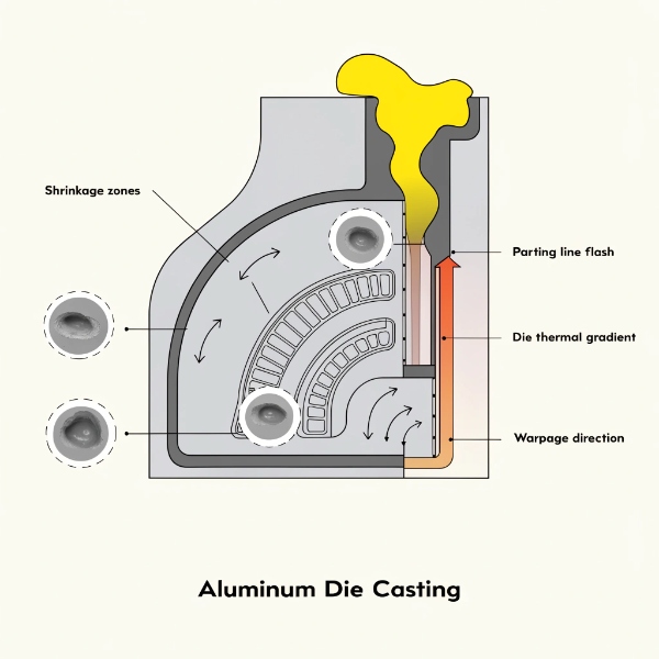
The parting line is the single largest source of tolerance loss in die casting. Three mechanisms:
- Flash: Molten metal escapes the parting line during intensification. Even thin flash (0.1–0.3 mm) adds material that distorts the part dimension near the line.
- Mismatch: The two die halves shift relative to each other during operation due to die clearance, tie-bar elongation, and guide pin wear. NADCA allows ±0.13 mm mismatch for standard parts; we target ±0.05 mm on critical faces.
- Die deflection: During the 40–100 MPa injection pressure, the die blocks flex outward. A 1000 mm die under 800T clamp force deflects measurably — this "breathing" directly affects the cavity dimension.
DFM rule we enforce: Never place a critical dimensional feature on or across the parting line. If a bearing bore must cross the parting line, machine it. No amount of die tuning compensates for parting line flash on a tolerance-critical surface.
4. Warpage and Residual Stress
A die casting solidifies from the outside in. Thin sections freeze first; thick sections freeze last and pull on the already-solid thin sections. The result is warpage — the part distorts after ejection as it cools to room temperature.
| Wall Section Ratio (thickest:thinnest) | Warpage Risk | Typical Distortion (200 mm part) |
|---|---|---|
| <2:1 | Low | <0.2 mm |
| 2:1–4:1 | Medium | 0.2–0.5 mm |
| 4:1–6:1 | High | 0.5–1.0 mm |
| >6:1 | Severe | >1.0 mm, redesign required |
Warpage is managed through DFM (uniform wall sections, transition radii, ribs placed to balance thermal paths) and process control (controlled die temperature, optimized cycle time, and in some cases fixtured cooling for geometrically complex parts).
Tooling Engineering: Where Tolerance Begins
A die casting can never be more dimensionally stable than the die that produced it. Tooling is the foundation, and three engineering decisions made at tool design lock in the tolerance floor:
Die Steel and Heat Treatment
H13 hot-work tool steel is the industry standard for aluminum die casting dies. But not all H13 is equal:
- Standard H13 (~44–48 HRC): Adequate for 50,000–100,000 shots before measurable wear begins affecting dimensions
- Premium H13 with optimized vanadium content (48–50 HRC): Extends wear life to 150,000–200,000 shots, maintaining dimensional stability longer
- Surface treatments (nitriding, PVD coatings): Reduce thermal fatigue cracking and abrasive wear from aluminum, extending the period between refurbishments
Die wear directly degrades tolerance over the life of the tool. A cavity dimension that holds ±0.15 mm at shot 5,000 may drift to ±0.25 mm by shot 80,000 if wear is not monitored and compensated. This is why we track dimensional drift via CMM on a sampling plan throughout the die life, and refurbish (weld + re-EDM or re-machine) before drift exceeds 50% of the tolerance band.
Cavity Surface Machining Precision
The cavity is machined by high-speed milling and/or EDM. The precision of this operation sets the ceiling on as-cast tolerance:
| Cavity Machining Method | Surface Finish | Dimensional Precision | Typical Use |
|---|---|---|---|
| High-speed milling (5-axis) | Ra 0.4–0.8 µm | ±0.01–0.02 mm | Critical cavity surfaces, cores |
| EDM (sinker) | Ra 0.8–1.6 µm | ±0.02–0.03 mm | Deep pockets, complex ribs |
| Wire EDM | Ra 0.8–1.2 µm | ±0.01 mm | Core inserts, precision apertures |
The die cavity is machined to a tolerance 5–10× tighter than the part tolerance it needs to hold. A ±0.15 mm part dimension requires a ±0.015–0.03 mm cavity dimension, because the die must absorb shrinkage variation, thermal expansion, and wear without consuming the full part tolerance.
Multi-Cavity Die Matching
For multi-cavity dies (2, 4, 6, 8 cavities), cavity-to-cavity variation is a critical issue. Each cavity is machined separately, and subtle differences in gate geometry, cooling line placement, and cavity surface condition create cavity-to-cavity dimensional variation.
We manage this through:
- Identical cavity machining: All cavities machined on the same 5-axis CNC in one setup batch
- Cavity-specific Moldflow validation: Each cavity is simulated independently to identify thermal differences
- Cavity-to-cavity CMM sampling: SPC tracks each cavity independently; if one cavity drifts, we identify and refurbish that cavity only, not the entire die
- Individual cavity identification: Each casting is marked with cavity ID (engraved or dot-marked) so dimensional data is traceable to the source cavity
Process Control: VHPDC and Shot Profile Stability
VHPDC’s Role in Dimensional Consistency
Vacuum High Pressure Die Casting (VHPDC) is primarily known for porosity reduction, but it also improves dimensional consistency. Standard HPDC traps air randomly — the amount and location of trapped gas varies shot to shot, which means effective metal pressure and fill density vary shot to shot. This translates directly to dimensional scatter.
VHPDC removes that variability:
| Metric | Standard HPDC | VHPDC |
|---|---|---|
| Shot-to-shot dimensional scatter (100 mm dim) | ±0.20–0.30 mm | ±0.10–0.15 mm |
| Porosity-driven density variation | 3–5% volume | <1–1.5% volume |
| Cp (100 mm dimension, 0.5 mm tolerance) | 0.8–1.0 | 1.3–1.6 |
A Cp of 1.33 (the IATF 16949 minimum for ongoing production) is achievable as-cast on a well-tooled VHPDC line for most linear dimensions. Without VHPDC, achieving Cp 1.33 as-cast requires either a looser tolerance band or 100% sorting.
Shot Profile Control
The injection profile — slow shot velocity, fast shot velocity, switching point, and intensification pressure — directly affects dimensions. Key sensitivities:
- Slow shot velocity: Too fast → premature turbulence and air entrapment; too slow → premature solidification and cold shut. Both cause dimensional variation.
- Switching point (slow→fast): If the switch happens too early, the die fills turbulently; too late, the metal begins freezing before intensification. The correct switching point is tied to the fraction of die cavity filled, typically 20–40%.
- Intensification pressure: Higher pressure (60–100 MPa) reduces shrinkage and improves dimensional repeatability, but requires sufficient clamp force to prevent die deflection.
At EMP Tech, all 13 die cast islands feature closed-loop shot control with real-time monitoring of velocity, pressure, and position. Deviation from the validated shot profile triggers automatic rejection of the casting — we do not rely on after-the-fact inspection to catch process drift.
Die Temperature Stability
Die temperature is monitored via thermocouples embedded in the die at 4–12 locations depending on die complexity. Temperature data feeds back to the thermal control system (hot oil heating + water cooling) within each cycle.
| Die Temperature Parameter | Target | Effect on Dimensional Scatter |
|---|---|---|
| Cavity surface temperature | 200–260°C (alloy-dependent) | Stable temp = stable shrinkage |
| Cycle-to-cycle variation | <±5°C | Reduces shot-to-shot scatter |
| Cavity-to-cavity variation | <±10°C | Reduces multi-cavity scatter |
| Die entry temperature (start of shift) | Within 10°C of steady-state | Eliminates "warm-up drift" |
Machining Strategy: From Casting to Final Tolerance
Single-Setup 5-Axis CNC
The single most effective tolerance strategy for die castings is machining all critical features in one setup on a 4/5-axis CNC. Here is why:
Every time a part is unclamped and re-fixtured, you lose datum alignment. A typical 3+2 machining strategy (machine one face, flip, machine another) accumulates:
- Datum shift: ±0.02–0.05 mm per re-fixturing
- Angular error: ±0.05–0.1° per re-fixturing
- Setup time: 5–15 minutes per setup
With single-setup 5-axis machining, all critical features (bearing bores, mating faces, bolt patterns, gasket grooves) are machined from one clamping reference. The positional relationship between features is held by the machine, not by the fixture.
| Machining Strategy | Setups | Position Tolerance (bore-to-bore, 150 mm) | Flatness (mating face, 200 mm) | Setup Time |
|---|---|---|---|---|
| 3-axis, multiple setups | 3–4 | ±0.10–0.15 mm | 0.05–0.08 mm | 45–60 min |
| 3+2 indexing (4-axis) | 2 | ±0.05–0.08 mm | 0.03–0.05 mm | 20–30 min |
| Full 5-axis, single setup | 1 | ±0.02–0.03 mm | 0.01–0.02 mm | 5–10 min |
EMP Tech operates 150+ 4/5-axis CNC centers, and the standard for all CTF (critical-to-function) features on EV housings is single-setup 5-axis machining. This is not a luxury — it is the only way to consistently hold the positional tolerances that Tier 1 drawings specify.
Datum Strategy: Casting vs Machining Datums
The choice of datum reference frame determines whether the part will machine successfully. Two principles we enforce:
Locate on as-cast features, machine from machined datums. The casting is located in the CNC fixture using robust as-cast surfaces (typically a 3-2-1 location scheme on non-critical faces). The first machining operation creates precision datums on the part. Subsequent operations locate on those machined datums.
Never use a parting-line surface as a datum. Parting-line flash and mismatch make unreliable datums. Always use a machined surface or a cored feature with controlled geometry.
In-Process Gauging
For high-volume programs, we deploy in-process probing on the CNC machine. The probe measures critical features before the part is unclamped, providing:
- Real-time dimensional feedback to the machine controller for tool wear compensation
- 100% inspection of CTF dimensions on every part (vs sampling)
- Statistical process control data tied to machine, tool, and casting lot
| Gauging Method | Coverage | Response Time | Typical Application |
|---|---|---|---|
| In-process probing (on CNC) | 100% of CTF features | Real-time (seconds) | High-volume, tight tolerance |
| Offline CMM (Zeiss) | Sampling (e.g., 1 in 20) | 5–15 min per part | Initial PPAP, engineering changes |
| Inline SPC gauge (hard gauge) | 100% of key dims | Seconds | High-volume, single dimension |
Measurement and SPC
CMM Strategy
Zeiss CMM (coordinate measuring machines) provide the dimensional truth for die castings. But CMM strategy matters as much as having the machine:
- Sampling plan: CMM measurement is time-consuming (5–30 min per part depending on feature count). For ongoing production, we sample 1 in 20 to 1 in 50 parts depending on process capability. For PPAP, we measure 100% of critical dimensions on a minimum sample of 30 parts.
- Measurement uncertainty budget: CMM measurement uncertainty for a 100 mm dimension is typically ±0.003–0.005 mm — far below the tolerance band. But measurement strategy (probing direction, stylus length, temperature compensation) must be controlled to realize this.
- Temperature-controlled measurement: Parts must be stabilized to 20°C before CMM measurement. A die casting at 30°C measures approximately 0.022 mm larger per 100 mm than at 20°C (coefficient of thermal expansion: 22 µm/m·°C).
Capability Targets
| Tolerance Type | Cp Target | Cpk Target | IATF 16949 Requirement |
|---|---|---|---|
| As-cast linear (NADCA std.) | ≥1.33 | ≥1.33 | Ppk ≥1.67 at PPAP |
| Machined CTF dimension | ≥2.0 | ≥1.67 | Ppk ≥1.67 at PPAP |
| Position (GD&T) | ≥1.67 | ≥1.33 | Ppk ≥1.67 at PPAP |
Gage R&R
Before any dimensional data is accepted as valid, the measurement system must pass Gage R&R (Repeatability and Reproducibility):
- Acceptable: Gage R&R <10% of tolerance band
- Conditionally acceptable: 10–30% (requires justification, used for non-critical dimensions)
- Unacceptable: >30% (measurement system must be improved)
For a ±0.15 mm tolerance (0.30 mm total band), Gage R&R must be <0.030 mm (30 µm). This requires a properly maintained CMM with calibrated styli, temperature-controlled environment, and trained operators.
DFM Considerations: Designing for Tolerance
The most effective tolerance strategy is not process control — it is design. The following DFM rules, applied during design review, prevent tolerance problems before they reach the foundry.
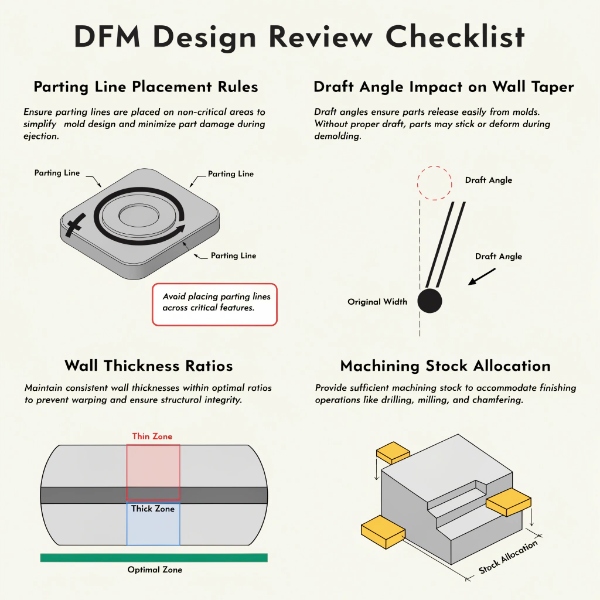
Parting Line Placement
| Rule | Rationale |
|---|---|
| No critical dimension crosses the parting line | Flash and mismatch degrade ±0.05–0.15 mm |
| Parting line on non-functional surface | Eliminates flash cleanup on mating faces |
| If a bore must cross the line, add machining stock | Machine to final tolerance after casting |
Draft Angles
Draft is required for ejection — typically 1–2° per side on as-cast surfaces. Draft directly affects the ability to hold tight tolerances on drafted walls:
- A 1° draft on a 50 mm deep wall creates 0.87 mm of taper per side
- A 0.5° draft (achievable with texture-free surfaces and good ejector design) reduces this to 0.44 mm
- If the drafted wall is a functional surface, it must be machined to remove taper
| Draft Angle | Wall Depth (mm) | Taper per Side (mm) | Impact on Tolerance |
|---|---|---|---|
| 2° (standard) | 50 | 1.75 | Unusable as functional surface |
| 1° (typical) | 50 | 0.87 | Requires machining if functional |
| 0.5° (optimized) | 50 | 0.44 | Borderline for non-mating features |
| 0° (not possible) | — | — | Part cannot eject |
Wall Thickness Uniformity
The single most impactful DFM rule for tolerance: keep wall sections uniform. Differential solidification is the root cause of warpage, and warpage consumes tolerance faster than any other mechanism.
- Target wall thickness ratio (thickest:thinnest) ≤ 2:1
- Transition between sections with radii ≥ 1.0× the thinner wall
- Use ribs instead of thickening sections to add stiffness
- Core out thick sections wherever possible
Real Tolerance Data: What We Actually Achieve
This table represents empirical data from EMP Tech production programs (EV motor housing, inverter housing, transmission housing) at steady-state production:
| Feature | Nominal Dimension | As-Cast Tolerance (achieved) | Machined Tolerance (achieved) | Process |
|---|---|---|---|---|
| Overall length (motor housing) | 280 mm | ±0.40 mm (Cp 1.35) | ±0.03 mm (Cp 2.8) | VHPDC + 5-axis CNC |
| Bearing bore diameter (Ø80) | 80 mm | ±0.25 mm (Cp 1.2) | H7 (+0.030/0) (Cp 2.1) | Boring, single setup |
| Bearing bore position (2 bores, 180 apart) | 180 mm | ±0.35 mm | ±0.03 mm (Cp 1.9) | 5-axis, single setup |
| Mating face flatness | 220 mm | 0.35 mm | 0.02 mm (Cp 2.5) | Face milling |
| Bolt pattern position (8 holes) | Ø150 PCĐ | ±0.30 mm | ±0.05 mm (Cp 1.8) | Drilling, single setup |
| Gasket groove width | 6 mm | — | +0.03/0 mm (Cp 2.2) | Slot milling |
| Surface roughness (mating) | — | Ra 3.2–6.3 µm | Ra 0.8 µm | Face milling |
Note: Cp values are calculated at steady-state production with validated die and tooling. Initial PPAP Ppk values are typically 10–15% lower due to die break-in effects.
Cost and Lead Time Implications
| Tolerance Strategy | Added Cost (% of part) | Tooling Lead Time | Measurement Cost | Typical Application |
|---|---|---|---|---|
| As-cast only (NADCA standard) | 0% | Standard | Low (sampling) | Non-functional brackets, covers |
| As-cast + selective CNC | +15–25% | Standard +2–3 weeks | Medium | Structural brackets with mating faces |
| Full CNC on CTF features | +30–45% | Standard +3–4 weeks | High (100% probing) | EV motor/inverter housings |
| Conformal cooling die + full CNC | +50–65% | +8–12 weeks tooling | High | Ultra-high-volume tight tolerance |
The pragmatic approach for most Tier 1 EV housing programs: VHPDC casting + single-setup 5-axis CNC on CTF features + in-process probing. This delivers Cp ≥2.0 on critical dimensions, holds IATF 16949 Ppk ≥1.67 at PPAP, and does not require conformal cooling unless volumes exceed 200,000 units/year or the part geometry is thermally extreme.
EMP Tech Tolerance-Relevant Capabilities
| Capability | Contribution to Tolerance |
|---|---|
| VHPDC (13 islands, 350T–3050T) | Reduces shot-to-shot scatter by ~50% vs standard HPDC |
| Moldflow shrinkage simulation | Zone-by-zone shrinkage compensation in die design |
| Zoned die thermal control | ±10–15°C cavity uniformity, reduced scatter |
| 5-axis CNC (150+ machines, single setup) | ±0.02–0.03 mm position tolerance on CTF features |
| In-process probing | 100% CTF inspection, real-time tool wear compensation |
| Zeiss CMM | ±0.003–0.005 mm measurement uncertainty at 20°C |
| IATF 16949:2016 + VDA 6.3 Grade A | Process discipline for Cp/Cpk targets |
| PPAP Level 3 | Full dimensional capability documentation at launch |
| Cavity-to-cavity SPC tracking | Individual cavity identification and drift monitoring |
Key Takeaways
- Die casting is a near-net-shape process, not a precision process. As-cast tolerances are ±0.2–0.4 mm on 100 mm dimensions — one to two orders of magnitude looser than machined tolerances. Design accordingly: specify tight tolerance only on CTF features, and machine those.
- Four variables control as-cast tolerance: shrinkage, die thermal balance, parting line effects, and warpage. Address all four — any one left unmanaged will consume your entire tolerance band.
- VHPDC reduces dimensional scatter by approximately 50% compared to standard HPDC, making Cp 1.33 achievable as-cast on most linear dimensions.
- Single-setup 5-axis CNC is the most effective tight-tolerance strategy. It eliminates re-fixturing error and holds bore-to-bore positional tolerance at ±0.02–0.03 mm.
- DFM is cheaper than process control. Uniform walls, parting line placement, and draft management prevent tolerance problems at zero added unit cost — this is the first conversation in every tolerance-critical program review.


