

What This Workflow Covers
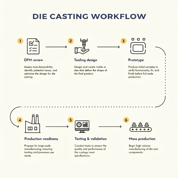
The path from a CAD model to a validated, mass-produced aluminum die casting involves six engineering stages — DFM review, moldflow simulation, tooling design and build, trial shots, PPAP qualification, and series production launch. Each stage has specific deliverables, decision gates, and failure modes. Skipping or compressing any stage introduces risk that compounds downstream: a DFM error caught at T1 costs 10× more to fix than at the review stage; the same error caught at SOP costs 100× more.
At EMP Tech, we run this workflow on every new part number — whether it is a 2 kg motor housing or a 35 kg battery tray. The process is governed by IATF 16949 APQP (Advanced Product Quality Planning) requirements and typically takes 12–16 weeks from DFM kickoff to PPAP approval for a well-engineered part. This article documents each stage with the actual deliverables, timelines, and quality gates we use.
Stage 1: DFM Review and Moldflow Simulation (Weeks 1–3)
What Happens
Before any tooling steel is cut, our engineering team conducts a structured Design for Manufacturing (DFM) review against the customer’s 3D model and 2D drawing. The DFM review identifies potential defects — shrinkage porosity, cold fills, warpage, soldering — and prescribes design or process modifications to eliminate them. A structured DFM review can eliminate 60–80% of potential defects before they reach trial shots, as we explain in our article on how DFM analysis reduces die casting defects.
DFM Review Checklist
| DFM Element | What We Check | Risk If Skipped |
|---|---|---|
| Wall thickness uniformity | Transitions ≤3:1 ratio, minimum 1.2 mm for VHPDC | Shrinkage porosity at thickness transitions |
| Draft angles | ≥1.0° per side (standard), ≥1.5° for deep cores | Sticking, drag marks, distortion at ejection |
| Fillet radii | ≥0.5 mm minimum, ≥1.0 mm at stress concentration points | Stress cracks, fatigue initiation sites |
| Undercuts and side cores | Minimize side core count; evaluate mechanical vs. hydraulic | Tooling complexity, cycle time, failure rate |
| Parting line location | Place on non-critical surfaces, avoid sealing grooves | Flash on functional surfaces, leak paths |
| Gate design and location | Optimize fill pattern, avoid jetting and turbulence | Cold fills, entrapped air, oxide inclusions |
| Overflow and vent placement | Place at last-fill areas, far from gates | Porosity at critical features |
| Cavity count and layout | Determine based on part size, press tonnage, volume | Underutilized press capacity, excessive cycle time |
Moldflow Simulation
After the DFM review, we run moldflow simulation using Magma or Flow-3D to model:
- Fill pattern: Verify metal flows from gate to last-fill area without jetting or early solidification
- Solidification: Identify hot spots where shrinkage porosity will form; design chills or feeding to compensate
- Distortion prediction: Calculate warpage from differential solidification; compensate in tooling geometry
- Thermal balance: Design cooling channel layout for uniform die temperature (±15°C target)
| Simulation Deliverable | Purpose | Acceptance Criterion |
|---|---|---|
| Fill animation | Verify progressive fill, no turbulence | Fill time <40 ms for 2 mm wall |
| Solidification map | Identify hot spots | No isolated liquid pools at critical features |
| Porosity prediction | Locate predicted porosity zones | Porosity <0.5% at critical surfaces |
| Warpage analysis | Predict dimensional deviation | Deviation within drawing tolerance after tooling compensation |
Stage 1 Gate: DFM Sign-Off
The DFM review concludes with a formal sign-off document listing all identified issues, proposed modifications, and customer-approved design changes. No tooling order is released without customer DFM sign-off.
Stage 2: Tooling Design and Manufacturing (Weeks 3–10)
Tooling Design
Tooling design translates the DFM-approved geometry into a physical die with:
- Cavity inserts: H13 or SKD61 hot-work tool steel, hardened to HRC 46–48
- Core pins and sliders: H13 with nitrided surface (nitride depth 0.15–0.25 mm) for wear resistance
- Cooling channels: Drilled or conformal channels targeting ±15°C die temperature uniformity
- Ejector system: Ejector pin count and placement calculated from ejection force simulation
- Gating system: Designed from moldflow results — gate area, runner geometry, overflow volumes
| Tooling Component | Material | Hardness | Lifetime Target |
|---|---|---|---|
| Cavity inserts | H13 / SKD61 | HRC 46–48 | 100,000–500,000 shots |
| Core pins | H13 (nitrided) | HRC 46–48 + nitride | 50,000–200,000 shots |
| Sliders | H13 (nitrided) | HRC 46–48 + nitride | 50,000–150,000 shots |
| Ejector pins | SKD61 | HRC 50–52 | 50,000+ shots |
| Die base | 1045 carbon steel | — | 10+ years |
Tool Manufacturing Process
Our tool shop follows a 6–8 week manufacturing sequence:
- Rough machining (Week 1–2): CNC milling of cavity inserts, core pins, and die base components
- Heat treatment (Week 2–3): Vacuum hardening of H13 to HRC 46–48, followed by triple tempering for dimensional stability
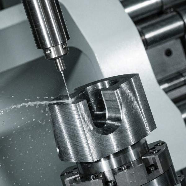
- Finish machining (Week 3–5): 5-axis CNC hard milling to final geometry, holding ±0.01 mm tolerance on critical surfaces
- EDM (Week 4–6): Sinker EDM for deep pockets, ribs, and features inaccessible to milling; wire EDM for ejector pin holes and cooling channel connections
- Polishing and texturing (Week 5–7): Manual polishing to specified surface finish (Ra 0.4–1.6 µm); media blasting or chemical etching for cosmetic textures
- Assembly and try-out setup (Week 6–8): Die assembly, cooling system pressure testing (at 50 bar), ejector system function check
Stage 2 Gate: Tool Inspection
Before the die leaves the tool shop, it undergoes full CMM inspection:
- Cavity geometry verified against CAD model within ±0.02 mm
- Parting line flatness ≤0.01 mm
- Core pin fit-up verified (no flash gap)
- Cooling channel flow rate tested (target: 15–20 L/min per channel)
Stage 3: Trial Shots — T1, T2, T3 (Weeks 10–14)
Trial Shot Philosophy
Trial shots are not "we tried and it worked." They are structured sampling events with specific objectives, acceptance criteria, and documentation. Each trial is a gate: if acceptance criteria are not met, the die returns to the tool shop for modification before the next trial.
T1: First Shot (Week 10–11)
Objective: Verify basic fill, ejection, and dimensional proximity.
| T1 Assessment | Method | Target |
|---|---|---|
| Fill completeness | Visual inspection, weight check | 100% fill, no short shots |
| Surface quality | Visual + 10x magnification | No cold shuts, flow marks on critical surfaces |
| Ejection | Visual | Part ejects freely, no distortion, no drag marks |
| Dimensional check | CMM layout (15–30 features) | Within ±0.2 mm of nominal (preliminary) |
| Porosity | X-ray radiography (5 samples) | No concentrated porosity at critical features |
T1 typically reveals 3–8 issues requiring die modification: gate adjustments, overflow relocation, venting improvements, or minor geometry corrections on cores or sliders.
T2: Optimized Shot (Week 12–13)
Objective: Achieve dimensional compliance and porosity targets after T1 modifications.
| T2 Assessment | Method | Target |
|---|---|---|
| Dimensional compliance | CMM layout (full drawing dimensions) | 100% within drawing tolerance |
| Porosity verification | X-ray (10 samples) + sectioning (3 samples) | Porosity <0.5% at critical surfaces, <1 mL/100g overall |
| Surface finish | Profilometer | Ra within specification on all critical surfaces |
| Leak testing | Helium leak test (if sealed housing) | ≤1×10⁻⁶ mbar·L/s |
| Process parameters | Shot end position, intensification pressure, cycle time | Stable, repeatable within ±2% |
T2 is the critical gate. If dimensions, porosity, and leak integrity all pass, the part is ready for T3 — the PPAP qualification run. If not, T2 modifications address the remaining issues.
T3: PPAP Qualification Run (Week 13–14)
Objective: Produce the PPAP sample set under documented, repeatable conditions.
The T3 run produces 30–300 parts (depending on part size and customer requirements) under locked process parameters. These parts become the PPAP samples for dimensional layout, material certification, and functional testing. The process parameters set during T3 become the production standard — any deviation in series production triggers a documented engineering change.
Trial Shot Documentation
Every trial shot is documented with:
- Shot log: Shot number, die temperature, melt temperature, injection pressure, shot end position, cycle time
- Photographic record: Each sample photographed from 6 angles
- Dimensional layout report: CMM data vs. drawing tolerances, color-coded pass/fail
- X-ray and sectioning report: Radiograph images and metallographic section analysis
- Process parameter sheet: Locked parameters for next trial or production
Stage 4: PPAP Qualification (Weeks 14–16)
What PPAP Level 3 Includes
PPAP (Production Part Approval Process) Level 3 is the standard requirement for automotive die casting. It demonstrates that the production process — not just the tool — can consistently produce parts meeting all requirements. Our quality control system governs every PPAP element.
| PPAP Element | What It Proves | Key Content |
|---|---|---|
| Design record | Engineering requirements are understood and documented | 3D model, 2D drawing, revision level confirmed |
| Engineering change documents | Any approved deviations from the drawing | Deviation permits, ECN records |
| Customer engineering approval | Customer has reviewed and approved the design | Signed approval letter |
| DFMEA / PFMEA | Design and process failure modes are identified and mitigated | Top 10 RPN items with controls |
| Process flow diagram | Manufacturing sequence is documented | From melt to shipment, every operation |
| Process FMEA | Process risks identified, controls in place | Severity × Occurrence × Detection scoring |
| Control plan | How each characteristic is controlled in production | Characteristic class, method, frequency, reaction |
| Measurement system analysis (MSA) | Measurement uncertainty is quantified | Gage R&R <10% for critical dimensions |
| Dimensional layout (15–30+ measurements) | Parts meet all drawing dimensions | CMM report, color-coded pass/fail |
| Material test reports | Alloy chemistry and mechanical properties | Spectrometer analysis + tensile test |
| Performance test results | Functional testing (leak, burst, fatigue) | Helium leak, pressure test results |
| Initial process study | Process capability on key characteristics | Cpk ≥ 1.67 for critical, ≥1.33 for significant |
| Qualified laboratory documentation | Testing is performed by accredited labs | ISO 17025 scope or equivalent |
| Appearance approval (if applicable) | Cosmetic surfaces meet master sample | Visual comparison to AQP sample |
| Sample master and retention | Physical samples preserved | 1 master + 1 retention per part number |
| Master sample | Customer-approved reference part | Sealed and stored, signed by customer |
PPAP Gate: Customer Approval
PPAP Level 3 is submitted to the customer for review. Production approval is granted only after the customer signs the PSW (Part Submission Warrant). Any open issues — even minor — are tracked in an open issue list with closure dates.
Stage 5: Mass Production Launch (SOP)
Pre-Launch Readiness
Before the first production shot, we verify:
| Readiness Item | Verification Method | Pass Criterion |
|---|---|---|
| Tool condition | Cavity inspection, wear measurement | No deviation from PPAP tool state |
| Process parameters | Lock parameters from T3 | Shot end position ±0.5 mm, pressures within ±2% |
| Material certification | Spectrometer check on first melt | Within alloy specification (ADC12: Si 9.5–12%, Cu 1.8–3.5%) |
| Quality plan | Control plan deployed to operators | Every operator trained, signed |
| Traceability system | First-in-first-out lot tracking active | Material lot → shot → machining lot → shipment linked |
| Inspection setup | CMM program, X-ray program, leak test setup loaded | First-off inspection (FOI) passed |
First Production Run
The first production run after SOP is treated as an extended qualification:
- First-off inspection (FOI): Every dimension, every leak test on first 5 parts — verifies tool condition after PPAP
- ramp-up plan: Gradual volume increase over 2–4 weeks to allow process stabilization and operator learning curve
- SPC activation: Control charts live on all key characteristics from day one
- Daily quality review: First 30 days — daily scrap review, defect Pareto, corrective actions
Production Ramp Curve
| Ramp Phase | Volume (% of target) | Duration | Focus |
|---|---|---|---|
| Phase 1: Stabilization | 30–50% | Weeks 1–2 | Process stabilization, operator training, scrap reduction |
| Phase 2: Acceleration | 50–80% | Weeks 3–4 | Cycle time optimization, OEE improvement |
| Phase 3: Full rate | 80–100% | Week 5+ | Steady-state production, continuous improvement |
Stage 6: Continuous Improvement and Volume Scale
SPC and Process Monitoring
Every critical characteristic is monitored with SPC control charts throughout production:
| Characteristic Type | SPC Method | Action Limit | Response |
|---|---|---|---|
| Critical (safety, sealing) | X-bar/R, 100% measurement | Cpk <1.67 → action | Stop, investigate, correct |
| Significant (functional) | X-bar/R, sampling 5/lot | Cpk <1.33 → action | Investigate, adjust, re-verify |
| General (cosmetic) | Visual sampling | Defect rate >2% → action | Adjust process, inspect |
Defect Pareto and Root Cause Analysis
Monthly defect reviews drive continuous improvement:
- Data collection: Scrap and rework categorized by defect type (porosity, flash, cold fill, dimensional, surface)
- Pareto analysis: Identify top 3 defect types contributing 80% of total scrap
- Root cause analysis: 5-why analysis, Ishikawa diagram, DOE if needed
- Corrective action: Tool modification, process parameter change, or design change — documented in ECN
- Verification: Cpk re-validation, 30-day monitoring period
Tool Maintenance and Refurbishment Cycle
| Maintenance Type | Frequency | Content |
|---|---|---|
| Preventive (daily) | Every shift | Die release application, cavity cleaning, lubrication of sliders and ejectors |
| Periodic (per 10,000 shots) | Every 2–4 weeks | Cavity inspection, wear measurement, cooling channel descaling |
| Major refurbishment | 50,000–100,000 shots | Cavity re-polishing, pin replacement, slider re-fit, nitride re-application |
| Full overhaul | 150,000–250,000 shots | Insert replacement, core re-manufacturing, full CMM re-validation |
Our manufacturing facility maintains a dedicated tool maintenance team and in-house tool shop for rapid refurbishment, minimizing production interruption.
Workflow Timeline Summary
| Stage | Duration | Key Deliverable | Gate |
|---|---|---|---|
| 1. DFM + Moldflow | 3 weeks | DFM report, simulation results | Customer DFM sign-off |
| 2. Tooling design + build | 6–8 weeks | Completed die set, CMM inspection report | Tool inspection pass |
| 3. Trial shots (T1–T3) | 2–4 weeks | PPAP sample set, locked process parameters | T3 dimensional + porosity pass |
| 4. PPAP qualification | 2 weeks | PPAP Level 3 package | Customer PSW approval |
| 5. Mass production launch | Ongoing | First production run, SPC active | FOI pass, ramp curve on track |
| 6. Continuous improvement | Ongoing | SPC data, defect Pareto, Cpk ≥1.67 | Monthly review |
Total typical timeline: 12–16 weeks from DFM to PPAP approval for a well-engineered part. Projects requiring 3+ mold iterations extend to 20+ weeks and indicate that the DFM or moldflow stage was insufficient — which is why we invest heavily in Stage 1.
Design Decisions That Speed Up or Slow Down the Workflow
The decisions made during part design directly impact the workflow timeline. Understanding these relationships is why we involve our engineering team from the first contact — and why we cover part design principles in our guide to mastering part design for die casting.
| Design Decision | Workflow Impact | Timeline Effect |
|---|---|---|
| Uniform wall thickness (transitions ≤3:1) | Reduces shrinkage porosity risk, eliminates T2 iteration | Saves 1–2 weeks |
| Adequate draft (≥1.0°) | Eliminates sticking and ejection distortion | Saves 1 trial shot iteration |
| Parting line on non-functional surface | Avoids flash on sealing/gasket surfaces | Eliminates rework in production |
| Gate location optimized for fill | Fewer cold fills, fewer T1 modifications | Saves 1 week |
| Conformal cooling channels | Tighter thermal control, faster cycle time | Reduces ramp-up time |
| Excessive undercuts | Additional sliders, complexity, failure modes | Adds 2–4 weeks to tooling |
| Tighter-than-necessary tolerance | Requires additional machining operations or in-line CMM | Increases cost and cycle time |
Frequently Asked Questions
Q: How long does it take to go from prototype to mass production in die casting?
A: For a well-engineered aluminum die casting, 12–16 weeks from DFM review to PPAP approval: DFM and moldflow 3 weeks, tooling design and build 6–8 weeks, trial shots T1–T3 2–4 weeks, PPAP documentation 2 weeks. Projects requiring 3+ mold iterations extend to 20+ weeks, indicating insufficient DFM or moldflow analysis.
Q: What is a trial shot (T1, T2, T3) in die casting?
A: Trial shots are structured sampling events with specific objectives. T1 verifies basic fill and ejection. T2 achieves dimensional and porosity compliance after T1 modifications. T3 produces the PPAP sample set under locked, repeatable conditions. Each trial is a gate — if acceptance criteria are not met, the die returns for modification.
Q: What does PPAP Level 3 include for die casting?
A: PPAP Level 3 includes dimensional layout (15–30+ CMM measurements), design record, DFMEA/PFMEA, process flow diagram, control plan, measurement system analysis (gage R&R), material test reports, performance test results, initial process study (Cpk ≥ 1.67 critical, ≥1.33 significant), and master/retention samples. It is the standard automotive requirement.
Q: What is the ramp-up curve for die casting mass production?
A: Typical ramp: Phase 1 (30–50% of target volume, weeks 1–2) focuses on process stabilization and operator training. Phase 2 (50–80%, weeks 3–4) optimizes cycle time and OEE. Phase 3 (80–100%, week 5+) achieves steady-state production. The ramp allows process learning without overwhelming the quality system.
Q: How is tool maintenance scheduled in mass production die casting?
A: Daily preventive maintenance (die release, cleaning, lubrication) every shift. Periodic inspection (cavity wear measurement, cooling descaling) every 10,000 shots or 2–4 weeks. Major refurbishment (re-polishing, pin replacement) at 50,000–100,000 shots. Full overhaul (insert replacement, CMM re-validation) at 150,000–250,000 shots.


