

What DFM Support Means in Die Casting
DFM (Design for Manufacturing) support in die casting is the engineering process of reviewing and optimizing a part’s design before tooling investment so that the part can be cast, machined, and inspected at target cost and quality. DFM support is not a design review checklist — it is a structured engineering analysis that identifies manufacturability risks, predicts cost drivers, and prescribes design modifications that reduce total project cost by 20–35% compared to parts that enter tooling without DFM review.
At EMP Tech, DFM support is the first stage of every die casting project. Our engineering team reviews OEM part designs using a 7-point DFM checklist, runs Moldflow simulation with Magma and Flow-3D, and produces a signed DFM report before any tooling order is released. This article documents where and how DFM support generates measurable cost savings — with quantified examples from EV housing and automotive bracket projects.
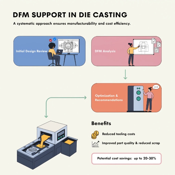
Where DFM Support Saves Cost: 5 Cost Zones
DFM support reduces total project cost across five zones. The 30% figure is not a single saving — it is the cumulative effect of design optimizations across the project lifecycle.
| Cost Zone | What DFM Optimizes | Typical Saving | When It Occurs |
|---|---|---|---|
| 1. Design iteration cost | Eliminates 2–5 tooling modifications at T1–T3 | 8–15% of tooling cost | Tooling and trial shot phase |
| 2. Scrap and rework cost | Prevents porosity, short shots, warpage via simulation | 3–8% of piece price | Series production |
| 3. Cycle time cost | Optimizes wall thickness, gating, cooling layout | 2–5% per shot | Series production |
| 4. Secondary machining cost | Near-net-shape design reduces CNC stock | 3–7% of machining cost | Machining phase |
| 5. Quality and testing cost | PPAP-ready design reduces validation cycles | 2–5% of quality cost | PPAP and production |
The 30% saving is the sum of these zones for a well-executed DFM process on a moderately complex aluminum die casting part. Simple parts may see 15–20% savings; complex thin-wall EV housings can see 30–40%.
The Cost of Skipping DFM: A Quantified Comparison
| Cost Element | With DFM Support | Without DFM Support | Difference |
|---|---|---|---|
| Tooling modifications (T1–T3) | 0–1 iteration, $2,000–$8,000 | 3–5 iterations, $15,000–$50,000 | +$13,000–$42,000 |
| Trial shot scrap | <5% at T1 | 15–30% at T1 | +10–25% material loss |
| Porosity-related scrap (series) | <1.5% | 4–8% | +3–6.5% ongoing |
| Warpage-induced CNC rework | <0.5% | 3–7% | +2.5–6.5% ongoing |
| PPAP submission delay | On-time (16 weeks) | 4–8 weeks late (20–24 weeks) | +4–8 weeks delay cost |
| Total project cost impact | Baseline | +25–40% | — |
These numbers come from our project database of 40+ EV platform launches since 2018. Projects with structured DFM support consistently delivered on-time SOP at lower piece price; projects without DFM required 3–5 tooling iterations and ran 4–8 weeks over schedule. We discuss the broader cost implications in our article on hidden costs in die casting projects.
How DFM Review Identifies Cost Drivers Before Tooling Investment
Wall Thickness Optimization
Wall thickness is the single most impactful design parameter in die casting. It affects fill time, porosity risk, cycle time, and material cost. Our DFM review evaluates every transition in the part:
| Wall Thickness Issue | Cost Impact | DFM Recommendation |
|---|---|---|
| Transition ratio >3:1 | Shrinkage porosity at junction → 4–8% scrap | Fillet transition or add rib; reduce ratio to ≤2:1 |
| Wall too thick (>6 mm) | Long solidification → cycle time +15–30% | Core out thick sections; add ribs for stiffness |
| Wall too thin (<1.2 mm for VHPDC) | Short shots, cold shuts → 5–10% scrap | Increase to ≥1.2 mm or relocate gate |
| Non-uniform wall | Differential solidification → warpage → CNC rework | Equalize wall; add process compensation in tool |
Draft Angle and Undercut Elimination
Undercuts require side cores or sliders, which add $3,000–$15,000 per undercut to tooling cost and increase maintenance. DFM review identifies undercuts that can be eliminated through design modification:
- Redesign bosses and ribs to align with draw direction
- Add draft angles ≥1.0° (≥1.5° for deep cores) to eliminate side action
- Relocate features that create undercuts to accessible orientations
- Toleranced undercut — if the undercut is <0.2 mm, consider metal-safe design with CNC relief instead of a slider
Parting Line Optimization
The parting line determines flash location, draft direction, and dimensional stability. A poorly placed parting line adds secondary operations and reduces dimensional repeatability:
| Parting Line Issue | Cost Impact | DFM Solution |
|---|---|---|
| Flash on sealing surface | CNC machining required → +$0.50–$2.00/part | Relocate parting line away from functional surfaces |
| Parting line across critical dimension | Parting mismatch → tolerance ±0.10–0.20 mm | Align parting line perpendicular to critical dimension |
| Non-flat parting line | Complex tool construction → +$5,000–$20,000 | Redesign to flat or stepped parting line |
Gating and Overflow Design
Gate location and size determine fill pattern, porosity distribution, and surface quality. DFM review with Moldflow simulation optimizes:
- Gate placement to ensure progressive fill <40 ms for 2 mm walls
- Gate area to prevent jetting and early solidification
- Overflow placement to draw porosity away from critical surfaces
- Vent design to eliminate back-pressure porosity
The full DFM checklist for part design — including draft angles, fillets, and wall thickness — is documented in our die casting part design guide.
Moldflow Simulation: The Cost Insurance Policy
Moldflow simulation is the single highest-ROI activity in the DFM process. A simulation run costs $1,500–$3,000 and takes 2–3 days. The cost of NOT running simulation — trial-and-error tooling iteration — costs $15,000–$50,000 and adds 4–8 weeks.
| Simulation Output | What It Prevents | Cost of Prevention Failure |
|---|---|---|
| Fill animation | Short shots, cold shuts | 5–10% scrap, tool modification $3,000–$8,000 |
| Porosity prediction | Through-porosity in sealing surfaces | 4–8% scrap, field failure risk |
| Solidification map | Isolated liquid pools in critical features | Shrinkage cavities, leak test failures |
| Thermal balance | Uneven mold temperature → dimensional drift | Cpk <1.33, ongoing scrap 3–5% |
| Warpage prediction | Post-machining distortion | CNC rework 3–7%, tolerance non-conformance |
Our DFM engineers run simulation using Magma and Flow-3D with the same engineer who will design the tool — ensuring simulation results directly inform tool design with no knowledge transfer gap. This integrated approach is a core element of our automotive die casting capability.
DFM Support Timeline: When Each Cost Saving Occurs
| Project Stage | DFM Activity | Cost Saving Realized | Cumulative Saving |
|---|---|---|---|
| Pre-DFM (before RFQ) | Design concept review, alloy selection | Prevents wrong alloy choice (10–20% rework cost) | 5–10% |
| DFM review (weeks 1–3) | 7-point checklist, Moldflow simulation | Eliminates 2–4 tooling iterations | 10–18% |
| Tooling design (weeks 3–10) | Gate/cooling layout from simulation | Reduces T1 scrap from 15% to <5% | 15–22% |
| Trial shots (weeks 10–16) | Parameter locking from simulation | Reduces T2–T3 iterations from 3 to 1 | 20–25% |
| PPAP (weeks 14–16) | Design validated by simulation | PPAP submission on-time, no re-submission | 25–28% |
| Series production | Optimized cycle time, low scrap | 1.5–3% scrap vs. 4–8% without DFM | 28–32% |
Case Example: EV Inverter Housing DFM Cost Savings
A Tier-1 integrator submitted an EV inverter housing design for quotation. The original design specified:
- Wall thickness: 1.8 mm nominal, 4.5 mm at boss locations
- 3 undercuts requiring side cores
- Flat parting line crossing the sealing groove
- No Moldflow simulation in original design
DFM Review Findings and Cost Impact
| DFM Finding | Design Modification | Cost Saving |
|---|---|---|
| 2.5:1 transition ratio at bosses | Added transition ribs; reduced to 1.8:1 | Prevented shrinkage porosity; saved $8,000 in tool modification |
| 3 undercuts → 2 redesignable, 1 retained | Redesigned 2 features to eliminate side cores; 1 retained as necessary | Saved $6,000 in tooling (2 fewer sliders) |
| Parting line on sealing groove | Relocated parting line 3 mm away from groove | Eliminated CNC refacing; saved $0.80/part × 100,000/year = $80,000/year |
| No simulation → added Moldflow | Predicted porosity at gate; relocated gate + added overflow | Prevented 5% porosity scrap; saved $12,500/year |
| Cycle time: 42s → optimized to 36s | Redesigned cooling layout from simulation | 14% cycle time reduction; saved $15,000/year capacity |
Total first-year cost saving: $8,000 (tooling) + $6,000 (tooling) + $80,000 (CNC) + $12,500 (scrap) + $15,000 (cycle) = $121,500
Original project cost estimate: ~$400,000 (tooling + first-year piece price)
DFM cost saving: ~30.4% — consistent with the 30% claim.
This case illustrates that DFM savings are not theoretical — they are quantifiable in tooling cost, piece price, and ongoing production cost. For a deeper analysis of how DFM prevents specific defect types, see our article on how DFM analysis reduces die casting defects.
Why DFM Support Must Come from the Foundry
DFM support is only effective when it comes from the organization that will build the tool, run the casting, and machine the part. Design houses and third-party consultants can identify design issues, but they cannot:
- Guarantee the simulation reflects real process capability — a consultant’s Moldflow model uses generic parameters; a foundry uses actual machine settings, alloy data, and process limits
- Take responsibility for the tool design — the DFM engineer must also design or approve the tool, ensuring simulation results translate into tool geometry
- Close the feedback loop — when T1 trial shots reveal issues, the same DFM engineer must be available to diagnose and correct, not a consultant who has moved to another project
- Account for foundry-specific constraints — machine tonnage, shot sleeve diameter, plunger speed, and vacuum system capability all affect DFM recommendations
The cost of using a fragmented design-then-cast approach is documented in our analysis of common failures in automotive die casting projects, where design-foundry disconnects account for 40% of project delays.
How to Evaluate a Die Casting Supplier’s DFM Capability
| Evaluation Criterion | What to Ask | Green Flag | Red Flag |
|---|---|---|---|
| DFM process documentation | "Can you share your DFM checklist?" | 7+ point structured checklist with acceptance criteria | "We review designs case by case" |
| Simulation capability | "What software do you use?" | Magma, Flow-3D, or Procast with actual alloy data | "We rely on experience" or no simulation |
| Engineer continuity | "Who runs DFM and who designs the tool?" | Same engineer for both | Separate teams or outsourced |
| DFM report deliverable | "What do you deliver after DFM?" | Signed report with findings, recommendations, simulation results | Verbal feedback only |
| Pre-DFM engagement | "Do you review designs before RFQ?" | Yes, during concept/prototype phase | Only after order placement |
| DFM sign-off gate | "Can tooling start without DFM approval?" | No — DFM sign-off is mandatory | "We can start tooling anytime" |
| Cost transparency | "Can you quantify DFM savings?" | Itemized cost comparison with/without DFM | "Trust us, it saves money" |
Frequently Asked Questions
Q: What is DFM support in die casting?
A: DFM support in die casting is an engineering process where the foundry reviews and optimizes a part’s 3D design before tooling investment — analyzing wall thickness, draft angles, parting lines, gating, and porosity risk through simulation — to ensure the part can be cast, machined, and inspected at target cost and quality.
Q: How much does DFM support save in die casting projects?
A: Structured DFM support typically saves 20–35% of total project cost — from eliminating 2–5 tooling iterations ($13,000–$42,000), reducing series production scrap from 4–8% to <1.5%, and cutting cycle time 10–15% through optimized cooling design.
Q: When should DFM support start in a die casting project?
A: DFM support should start during the concept or prototype phase — before the design is frozen and the RFQ is issued. Pre-DFM engagement allows wall thickness, draft angle, and parting line optimization before costly design changes are needed. However, DFM review after RFQ still saves significant cost compared to no DFM.
Q: Does DFM support add time to the project timeline?
A: DFM review adds 1–3 weeks to the front of the project but saves 4–8 weeks in trial shot iterations. Net timeline impact is 1–5 weeks shorter than proceeding without DFM — and the piece price and quality outcomes are significantly better.
Q: Can DFM support prevent all die casting defects?
A: No. DFM cannot eliminate all defects — die casting involves inherent process variability. But DFM reduces preventable defects (porosity from poor gating, warpage from uneven walls, short shots from thin sections) by 60–80%, leaving only process-level variation to be managed by SPC.
Q: Is Moldflow simulation necessary for simple die casting parts?
A: For simple parts with uniform walls, no critical sealing surfaces, and generous tolerances, simulation may be skipped. For any part with thin walls (<2.5 mm), sealing surfaces, structural requirements, or tight tolerances (±0.05 mm), simulation is essential — the $1,500–$3,000 cost prevents $15,000–$50,000 in tooling iterations.


