

Most automotive die casting program failures we’ve seen don’t originate on the casting floor — they originate three to six months earlier, in decisions made during sourcing and DFM that nobody revisits until PPAP rejections or field failures force the issue. This article covers the failure patterns we see repeat across Tier 1 programs, organized by where in the program timeline they actually originate, not just where they show up.
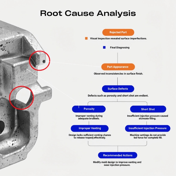
Failure 1: Tolerance Specs Copied From a Different Process or Program
What happens: A drawing carries forward tolerance callouts from a machined-metal legacy part, or from a different casting program with different geometry, without validation against what HPDC can actually hold. The result is either an unachievable spec discovered at first-article inspection, or an achievable spec that’s needlessly tight and drives unnecessary machining cost.
How to avoid it: Every incoming drawing gets tolerance capability reviewed against ISO 8062-3 CT grades during DFM, feature by feature — not as a blanket sign-off. Parting-line-crossing dimensions, cored features, and post-machined features get flagged separately, because they don’t share the same capability ceiling. This should happen before quote finalization, not after tool-cut.
Failure 2: Gate and Runner Design Not Revisited for New Alloy or Geometry
What happens: A gating system that worked on a previous program gets reused on new tooling with a different wall thickness or alloy, on the assumption that "it worked before." Fill dynamics don’t transfer between geometries — a gate sized correctly for a 3mm wall underfills or overfills a 2mm wall zone, producing cold flow, flow lines, or localized porosity that only shows up at specific points in the part.
How to avoid it: Moldflow simulation runs on every new tool design regardless of how similar it looks to a prior program, with explicit validation of flow-length-to-wall-thickness ratio and fill-front velocity at every wall thickness transition — not just at the nominal wall section.
Failure 3: Porosity in Sealing or Structural Zones Discovered Late
What happens: Bulk porosity data looks acceptable on average, but a customer discovers post-machining that porosity intersects a sealing groove or bearing bore — a defect invisible until the casting is cut open by the CNC operation itself. This is one of the most expensive failure modes because it’s typically caught after value has already been added through machining.
| Detection Point | Cost to Fix | Typical Root Cause |
|---|---|---|
| Pre-machining X-ray (100% inspection) | Lowest — scrap raw casting | Gas/shrinkage porosity at known-risk zone |
| Post-machining leak test | Moderate — scrapped machined part | Porosity not visible until sealing plane cut |
| Field failure | Highest — containment, sorting, potential recall exposure | Undetected porosity in a zone not covered by inspection plan |
How to avoid it: Sealing and structural zones get identified during DFM specifically so Moldflow can steer last-fill/last-solidify zones away from them into overflow wells, and 100% X-ray/leak test coverage is scoped for those zones specifically — not sampled. Relying on bulk average porosity data as a proxy for zone-specific risk is how this failure mode gets missed.
Failure 4: Warpage and Dimensional Drift From Uncontrolled Cooling
What happens: Parts pass dimensional inspection immediately after machining but drift out of tolerance during transit or after assembly, because internal casting stress from uneven cooling wasn’t relieved before final inspection. This shows up as an intermittent, hard-to-diagnose customer complaint rather than a clean PPAP rejection.
How to avoid it: For dimensionally critical structural parts — motor housings, battery tray sections — we hold post-ejection constrained cooling on a check fixture for a defined dwell before proceeding to machining, and abrupt wall-thickness transitions get flagged during DFM as warpage risk zones requiring a transition radius.
Failure 5: Tool Wear Not Caught Before It Affects Dimensional Output
What happens: Cavity wear, core pin deflection, and heat-checking progress gradually, and if PM intervals are based on a generic OEM schedule rather than the specific tool’s stress profile, dimensional drift creeps in slowly enough that it’s missed by spot-check inspection until a batch is already at the customer.
| Tool Stress Factor | Elevated Risk Without Adjusted PM Schedule |
|---|---|
| Thin-wall zones (see wall-thickness content) | Faster heat-checking at high-velocity gate areas |
| High-volume, high-cycle-rate programs | Cumulative cavity wear outpaces generic OEM interval |
| Deep cored features | Core pin deflection drift over shot count |
How to avoid it: PM intervals are set per tool family based on actual stress profile (wall thickness, cycle rate, core depth), not a single generic schedule across all tooling, and CMM sampling frequency increases as a tool approaches its historical wear-pattern threshold rather than staying flat across the tool’s life.
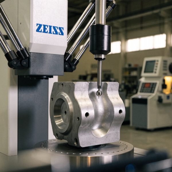
Failure 6: Engineering Changes Implemented Without Full Re-Validation
What happens: A minor-seeming dimensional or gate change gets implemented, but the ripple effect on fill dynamics, cooling balance, or ejection isn’t re-simulated — so a change that fixes one dimension introduces a new defect elsewhere in the part that isn’t caught until the next full inspection cycle.
How to avoid it: Any change affecting cavity geometry triggers a defined re-validation scope (Moldflow re-run if fill path is affected, full CMM re-qualification, PPAP re-submission if the change is customer-facing) agreed in the ECN process before tool modification begins — not decided ad hoc per change based on how "minor" it looks.
Failure 7: Alloy Substitution Without Fluidity or Mechanical Re-Qualification
What happens: A lower-cost or recycled-content alloy gets substituted for cost reasons without re-validating fluidity margin (critical at thin-wall zones) or mechanical properties (critical for structural/crash-relevant parts), because the substitute alloy is assumed to be "close enough" to the original spec.
How to avoid it: Any alloy substitution is treated as a new material qualification, not a swap — fluidity is re-validated specifically at the tightest wall-thickness zone in the part, and mechanical properties (elongation, yield strength) are re-tested against the part’s actual functional requirement, not just against a generic alloy datasheet.
Bottom Line
Nearly every recurring failure mode in automotive die casting traces back to a decision that skipped process-specific validation — a tolerance copied without checking casting capability, a gate design reused without re-simulating flow, an alloy swapped without re-qualifying fluidity, a change implemented without re-validating the whole part, not just the changed feature. The common thread across all of these: the fix is almost always cheaper during DFM or the ECN review than after PPAP, and the programs that avoid these failures are the ones that treat every geometry, alloy, or design change as requiring its own validation cycle rather than assuming precedent from a similar prior program.


