

What EV Project Support Means
Supporting an EV (electric vehicle) project from DFM (Design for Manufacturing) to mass production means taking engineering responsibility for the complete lifecycle of an aluminum die casting — from the first design review to the millionth production shot. This is not a transactional supplier relationship. It is a co-engineering partnership where the die casting supplier’s technical team works alongside the OEM’s design, quality, and manufacturing engineers to ensure that the part is castable, machinable, testable, and deliverable at target cost and quality.
At EMP Tech, our EV project support covers four housing categories — motor housings, inverter/converter housings, battery enclosures, and PDU housings — across 13 VHPDC die casting islands and 150+ CNC machining centers. We have supported 40+ EV platform launches since 2018, producing parts for Tier-1 system integrators serving European and North American OEMs. This article documents the support model we apply at each project stage.
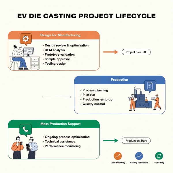
Stage 1: Pre-DFM Engagement (Before RFQ)
Why Early Engagement Matters
The most impactful engineering decisions in a die casting project are made before the RFQ is issued. By the time a part design reaches the RFQ stage, wall thicknesses, draft angles, fillet radii, and parting line locations are often locked — and many of these design choices were made without manufacturing input. Our engineering team engages with OEM design teams during the concept and prototype stages to provide manufacturing feedback before designs are frozen.
What We Provide in Pre-DFM Engagement
| Service | Deliverable | Impact |
|---|---|---|
| Manufacturing feasibility review | Preliminary DFM assessment of 3D model | Identifies castability risks before design freeze |
| Alloy selection consultation | Recommendation based on functional requirements | Prevents wrong alloy choice that costs 10–20% extra in rework or process change |
| Process route recommendation | VHPDC vs. HPDC, machining strategy, testing plan | Aligns manufacturing method with part function |
| Cost driver analysis | Identification of top 5 cost drivers in the design | Enables design optimization for cost before tooling investment |
| Timeline validation | Verification that target SOP is achievable | Prevents unrealistic commitments — 12–16 weeks is standard, not 6 |
Pre-DFM Case Example: Motor Housing Wall Thickness
An OEM design team presented a motor housing with 2.0 mm nominal wall thickness and 4.0 mm thick boss features for bolt mounting. Our pre-DFM review identified that the 2:1 transition ratio would cause shrinkage porosity at the boss-to-wall junction. We recommended either thickening the nominal wall to 2.5 mm (reducing the transition ratio to 1.6:1) or adding a transitional rib between the boss and the wall. The OEM adopted the rib solution — no cost impact, zero tooling iterations on this feature at T1.
This is why early engagement matters. A DFM review at the concept stage costs nothing; the same fix at T1 costs 2 weeks and a tool modification. We cover this principle in detail in our article on how DFM analysis reduces die casting defects.
Stage 2: DFM Review and Moldflow Simulation (Weeks 1–3)
Structured DFM Review Process
Once the RFQ is awarded, we execute a structured DFM review with the following deliverables:
| DFM Deliverable | Content | Gate Criteria |
|---|---|---|
| Wall thickness analysis | Transition ratios, minimum thickness, thick-section hot spots | All transitions ≤3:1; min 1.2 mm for VHPDC |
| Draft angle verification | Per-surface draft assessment | ≥1.0° standard; ≥1.5° for deep cores |
| Parting line proposal | Parting line location with rationale | No flash on sealing or functional surfaces |
| Gate design proposal | Gate location, area, and fill direction | Progressive fill, no jetting |
| Porosity risk map | Identification of critical features at porosity risk | Porosity <0.5% at critical surfaces via overflow/vent design |
| Distortion prediction | Warpage analysis from differential solidification | Within tolerance after tooling compensation |
| Machining allowance verification | Material stock on machined surfaces | 0.3–0.8 mm stock, accessible in single setup |
Moldflow Simulation with Magma / Flow-3D
| Simulation Output | What It Predicts | Acceptance Target |
|---|---|---|
| Fill animation | Metal flow pattern, turbulence, early solidification | Progressive fill <40 ms for 2 mm wall |
| Solidification map | Hot spot locations, last-to-solidify zones | No isolated liquid at critical features |
| Porosity prediction | Size and location of predicted porosity | <0.5% at critical surfaces, <1 mL/100g overall |
| Thermal balance | Die temperature distribution | ±15°C uniformity with designed cooling channels |
| Warpage prediction | Dimensional deviation from nominal | Within drawing tolerance after geometry compensation |
DFM Sign-Off Gate
The DFM review concludes with a formal sign-off meeting with the customer’s engineering team. All identified issues are listed with proposed solutions, and the customer approves the design modifications before tooling is ordered. No tooling order is released without DFM sign-off — this is a non-negotiable gate in our APQP process.
Stage 3: Tooling Design and Build (Weeks 3–10)
Tool Design Philosophy
Our tooling design follows three principles:
- Thermal balance first: Cooling channel layout is designed before cavity geometry — the die must maintain ±15°C uniformity for dimensional stability and cycle time consistency
- Single-source accountability: The same engineer who ran the DFM and moldflow designs the tool — no knowledge transfer gap
- Maintainability built-in: Ejector pin placement, slider access, and wear plate design allow in-press maintenance without die disassembly
Tool Build Specifications
| Component | Material | Hardness | Lifetime |
|---|---|---|---|
| Cavity inserts | H13 / SKD61 | HRC 46–48 | 100,000–500,000 shots |
| Core pins | H13 (nitrided, 0.15–0.25 mm depth) | HRC 46–48 + nitride | 50,000–200,000 shots |
| Sliders | H13 (nitrided) | HRC 46–48 + nitride | 50,000–150,000 shots |
| Ejector pins | SKD61 | HRC 50–52 | 50,000+ shots |
| Die base | 1045 carbon steel | — | 10+ years |
Tool Build Timeline
| Week | Activity | Deliverable |
|---|---|---|
| 1–2 | Rough CNC machining of cavity, cores, die base | Geometry within 0.5 mm of final |
| 2–3 | Vacuum heat treatment (H13 → HRC 46–48, triple tempered) | Dimensionally stable hardened steel |
| 3–5 | 5-axis CNC hard milling to final geometry | ±0.01 mm tolerance on critical surfaces |
| 4–6 | Sinker EDM (deep pockets, ribs) + Wire EDM (ejector holes, cooling connections) | All internal features complete |
| 5–7 | Polishing (Ra 0.4–1.6 µm) + texturing | Surface finish to specification |
| 6–8 | Assembly, cooling pressure test (50 bar), ejector function check | Ready for T1 trial shot |
Stage 4: Trial Shots and PPAP (Weeks 10–16)
T1–T3 Trial Shot Process
Our trial shot process is documented in detail in our die casting workflow, but the key support elements for EV projects are:
| Trial | Objective | EV-Specific Focus | Gate |
|---|---|---|---|
| T1 | Verify fill, ejection, dimensional proximity | Cooling channel fill verification on motor housings; leak path identification on inverter housings | No short shots, free ejection |
| T2 | Dimensional + porosity compliance | Helium leak test ≤1×10⁻⁶ mbar·L/s on sealed housings; X-ray porosity <0.5% at critical surfaces | 100% dimensional pass, leak pass |
| T3 | PPAP sample run under locked parameters | 30–300 parts for PPAP submission; Cpk ≥1.67 on critical dimensions | PPAP sample set approved |
PPAP Level 3 Package
For EV projects, PPAP Level 3 is mandatory. We deliver the complete package:
- Design record (3D model + 2D drawing, revision confirmed)
- DFMEA + PFMEA (top 10 RPN items with controls)
- Process flow diagram (melt → cast → machine → test → pack → ship)
- Control plan (characteristic class, method, frequency, reaction plan)
- MSA (gage R&R <10% on critical dimensions)
- Dimensional layout (15–30+ CMM measurements, color-coded pass/fail)
- Material test reports (spectrometer + tensile per ASTM B557)
- Performance test results (helium leak, burst pressure, salt spray)
- Initial process study (Cpk ≥1.67 critical, ≥1.33 significant)
Stage 5: Series Production and Continuous Support
Production Launch Support
After PPAP approval and SOP, our support continues through the production lifecycle:
| Support Activity | Frequency | Purpose |
|---|---|---|
| Daily quality review | First 30 days | Scrap Pareto, defect root cause, corrective actions |
| Weekly SPC review | Ongoing | Cpk monitoring on all critical dimensions; action if Cpk <1.67 |
| Monthly defect review | Ongoing | Top 3 defect types, root cause analysis, ECN-driven improvements |
| Tool condition monitoring | Every 10,000 shots | Cavity wear measurement, cooling channel inspection |
| Tool refurbishment | 50,000–100,000 shots | Re-polishing, pin replacement, nitride re-application |
| Full tool overhaul | 150,000–250,000 shots | Insert replacement, full CMM re-validation |
SPC and Quality Monitoring
Our quality control system maintains continuous SPC on every critical characteristic:
| Characteristic Class | SPC Method | Action Limit | Response |
|---|---|---|---|
| Critical (sealing, safety) | X-bar/R, 100% measurement | Cpk <1.67 → stop | Investigate, correct, re-verify |
| Significant (functional) | X-bar/R, 5/lot sampling | Cpk <1.33 → action | Investigate, adjust, re-verify |
| General (cosmetic) | Visual sampling | Defect rate >2% → action | Adjust process, inspect |
Volume Scaling Support
| Volume Phase | Support Focus | Activities |
|---|---|---|
| 30–50% ramp | Process stabilization | Daily quality reviews, operator training, scrap reduction |
| 50–80% ramp | Cycle time optimization | Process parameter fine-tuning, OEE improvement |
| 80–100% ramp | Steady-state management | SPC monitoring, preventive maintenance, continuous improvement |
| Volume increase (new program) | Capacity verification | Press availability, tool duplication, operator cross-training |
EV Housing Types: How We Support Each
Motor Housing Support
| Support Element | What We Do | Why EV Motor Housings Need It |
|---|---|---|
| Cooling channel DFM | Verify spiral/axial water jacket castability; wall thickness 3–5 mm | Cast cooling channels must not leak — through-porosity = field failure |
| Stator bore machining | Single-setup 5-axis CNC boring to H7 tolerance | Roundness ≤0.03 mm; Ra 1.6 µm; impossible with multi-setup |
| 100% helium leak testing | Every housing tested at ≤1×10⁻⁶ mbar·L/s | Water jacket integrity is safety-critical |
| Thermal cycle validation | Verify housing survives thermal cycling (−40°C to +120°C, 1,000 cycles) | EV motor housings experience extreme thermal cycling |
Inverter/Converter Housing Support
| Support Element | What We Do | Why EV Inverters Need It |
|---|---|---|
| Flatness control on mounting face | 5-axis CNC single-setup machining; flatness ≤0.1 mm/100 mm | Power module thermal interface requires flatness for thermal transfer |
| EMI shielding verification | Casting integrity (no through-porosity) + surface treatment | CISPR 25 Class 5 shielding requires defect-free casting |
| Thin-wall VHPDC | 2.0–3.0 mm nominal wall with vacuum fill | Thin walls reduce weight; vacuum prevents fill defects |
| Connector sealing | O-ring groove tolerance ±0.02 mm | IP67/IP6K9K sealing for high-voltage connectors |
Battery Enclosure Support
| Support Element | What We Do | Why EV Batteries Need It |
|---|---|---|
| Large-tonnage casting | 2500T+ VHPDC press for 15–40 kg enclosures | Battery enclosures are the largest die castings in an EV |
| FSW (friction stir welding) | In-house or partner FSW for sealing joints | FSW enables hermetic sealing of multi-piece enclosures |
| Crashworthiness analysis | DFM review of rib design, material selection (AlSi10Mg) | Side pole impact and bottom-out resistance are regulatory requirements |
| IP67/IP6K9K validation | 100% leak testing + wash validation | Battery enclosures must survive high-pressure wash |
PDU Housing Support
| Support Element | What We Do | Why EV PDUs Need It |
|---|---|---|
| Dielectric integrity | Material purity control, inclusion monitoring | High-voltage insulation per ISO 6469-3 |
| Precision mounting | Position tolerance ±0.1 mm on mounting bosses | PDU internal components require precise positioning |
| Sealing verification | IP67 leak testing on 100% of housings | High-voltage components must be sealed from moisture |
Our EV Project Support Team
Dedicated Engineering Team Structure
| Role | Responsibility | When Engaged |
|---|---|---|
| Program manager | Overall project timeline, customer interface, escalation | From pre-DFM through SOP+ |
| Lead DFM engineer | DFM review, moldflow, tooling design approval | Stages 1–3 |
| Tool design engineer | Tooling design, cooling layout, gate design | Stage 3 |
| Process engineer | Trial shots, parameter locking, production setup | Stages 3–5 |
| Quality engineer | PPAP, SPC, control plan, Cpk monitoring | Stages 4–5+ |
| CNC programming engineer | Machining strategy, fixture design, single-setup optimization | Stages 3–5 |
| Tooling maintenance lead | Preventive maintenance, refurbishment scheduling | Stage 5+ |
Communication and Reporting
| Report | Frequency | Content |
|---|---|---|
| Project status report | Weekly (Stages 1–4), Daily (Stage 5 first 30 days) | Timeline, open issues, risk register |
| DFM report | One-time at Stage 2 | All design issues, proposed modifications, customer sign-off |
| Trial shot report | Per trial (T1, T2, T3) | Shot log, dimensional layout, X-ray, leak test results |
| PPAP package | One-time at Stage 4 | Full Level 3 documentation |
| Monthly production report | Monthly (Stage 5+) | Volume, scrap rate, Cpk trends, open actions |
Why Integrated Support Beats Fragmented Supply Chain
The Cost of Fragmented Supply Chain
| Fragmented Model | Problem | Impact on EV Projects |
|---|---|---|
| Design house → Caster → Machinist → Tester | Each handoff loses information and adds logistics time | 2–4 weeks longer timeline; dimensional drift at each handoff |
| Caster not involved in DFM | Tool designed without manufacturing input → 3–5 iterations | 4–8 weeks of extra trial shot time |
| Machinist separate from caster | Transport between sites → ±0.05–0.10 mm dimensional drift | Critical features (stator bore, mounting pads) out of tolerance |
| Quality system fragmented | No single accountable party for leak/porosity failures | Finger-pointing between caster and machinist; field failures |
| No tool maintenance team | Tool wear unmonitored → quality drift mid-production | Cpk drops below 1.67; scrap increases; customer complaints |
The Integrated Solution
Our manufacturing facility integrates die casting, CNC machining, and testing under one roof — with one engineering team, one quality system, and one point of accountability:
- Single DFM-to-production engineering chain: The engineer who runs the DFM review also approves the tool design and locks the process parameters — no knowledge transfer gaps
- 3–5 day casting-to-machining flow: No transport between sites; no dimensional drift from logistics handling
- Single quality system: One control plan, one SPC system, one accountable party for all quality outcomes
- In-house tool maintenance: Dedicated team and tool shop for rapid refurbishment — minimizing production interruption
- Full traceability: Material lot → melt → casting shot → machining lot → shipment — all linked in one system
The complete workflow from DFM to mass production is documented in our die casting workflow article, and our integrated approach to EV die casting is detailed on our EV solutions page.
Frequently Asked Questions
Q: When should we engage EMP Tech in our EV housing project?
A: Ideally during the concept or prototype stage — before the design is frozen and the RFQ is issued. Pre-DFM engagement allows us to provide manufacturing feedback on wall thickness, draft angles, and gating before costly design changes are needed. However, we also support projects at the RFQ stage if the design is already frozen — our DFM review will identify any remaining manufacturability issues.
Q: How long does it take from DFM to mass production for an EV housing?
A: 12–16 weeks for a well-engineered part: DFM and moldflow 3 weeks, tooling design and build 6–8 weeks, trial shots T1–T3 2–4 weeks, PPAP documentation 2 weeks. Projects requiring 3+ mold iterations extend to 20+ weeks — which is why we invest heavily in Stage 1 DFM to minimize iterations.
Q: Do you support EV projects with T6 heat treatment requirements?
A: Yes. T6 heat treatment (solution treatment at 500+°C followed by aging) requires VHPDC to prevent blistering from trapped gas. Our 13 VHPDC die casting islands all support vacuum processing, enabling T6 heat treatment for AlSi10Mg and A356 structural alloys — achieving elongation >8% and tensile strength >280 MPa required for crash-relevant battery housings.
Q: Can you handle both die casting and CNC machining for EV housings?
A: Yes — both are under one roof at our facility. We operate 13 VHPDC die casting islands (350T–3050T) and 150+ CNC machining centers (4/5-axis). Single-setup machining is our standard approach for critical features — the stator bore, mounting pads, and sealing grooves are all machined in one clamping to maintain positional relationships.
Q: What quality documentation do you provide for EV projects?
A: Full PPAP Level 3 — including dimensional layout (15–30+ CMM measurements), DFMEA/PFMEA, process flow diagram, control plan, MSA (gage R&R), material test reports, performance test results, and initial process study with Cpk ≥1.67 on critical dimensions. Our quality system is IATF 16949 certified and VDA 6.3 Grade A rated.


