

What Is Friction Stir Welding in Die Casting?
Friction Stir Welding (FSW) in die casting is a solid-state joining process where a rotating, non-consumable tool traverses the seam between two die-cast aluminum components — typically the cast base and a wrought or cast lid — generating frictional heat that plastifies the metal without melting it, then mechanically stirs the materials together to forge a homogeneous, void-free joint. Unlike MIG, TIG, or laser welding, FSW operates entirely below the melting point of aluminum (660°C), typically reaching 400–480°C at the weld nugget, which eliminates porosity, spatter, and thermal distortion.
In die casting applications, FSW serves one primary purpose: sealing cast housings that contain integrated cooling channels or electronics. The process enables the manufacture of water-cooled EV inverter housings, motor housings, and battery tray components where the cast base features internal coolant galleries that must be sealed with a lid plate to create a leak-tight assembly.
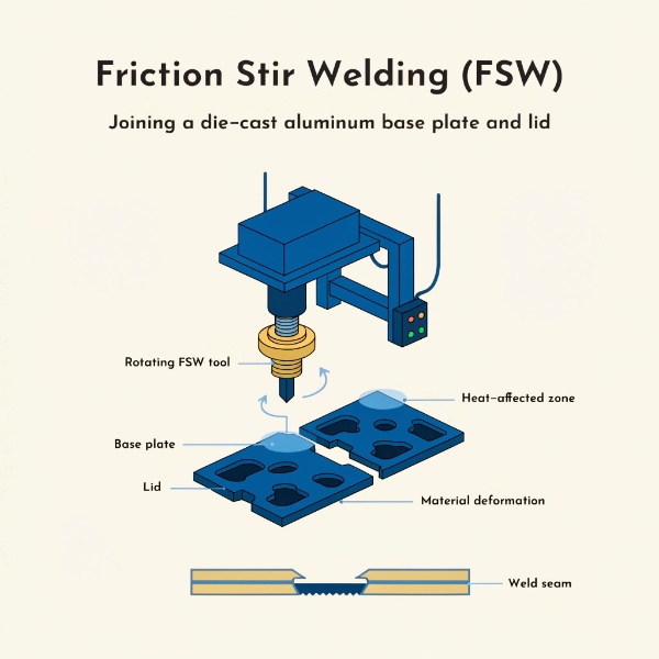
How FSW Works: The Solid-State Joining Mechanism
The FSW process uses a specially designed tool with two components: a shoulder that rides on the surface and a pin (probe) that penetrates the joint line. The mechanism proceeds in four phases:
| Phase | What Happens | Temperature | Duration |
|---|---|---|---|
| 1. Plunge | Rotating tool penetrates the joint line, generating frictional heat | 200–300°C | 3–5 s |
| 2. Dwell | Tool holds position, building heat to plastify the material | 350–420°C | 2–4 s |
| 3. Traverse | Tool moves along the seam, stirring plastified metal | 400–480°C | 10–60 s (depending on length) |
| 4. Withdraw | Tool retracts, leaving a solid forged joint | Cooling to ambient | 5–10 s |
The key insight is that the metal never melts. At 400–480°C, the aluminum becomes soft enough to deform plastically but retains its solid crystalline structure. The rotating pin mechanically intermixes the two surfaces at the molecular grain level, creating a forged bond that is:
- Void-free — no gas absorption because no melting occurs
- Porosity-immune — FSW is not affected by gas porosity in the parent die-cast material, because it operates below the melting point where gas does not expand
- Low-distortion — heat input is 60-80% lower than TIG welding, preserving dimensional accuracy
When to Use FSW in Die Casting: 5 Application Scenarios
Scenario 1: Sealing Water-Cooled EV Inverter Housings
EV inverter housings with integrated coolant galleries require a lid plate to seal the coolant channel. The lid must withstand 2–3 bar coolant pressure at 90°C continuous operating temperature, with thermal cycling from -40°C to +105°C. FSW is the industry-standard sealing method because it achieves helium leak rates below 1×10⁻³ mbar·L/s — a specification that MIG and TIG welding routinely fail at 8–15% rates due to porosity in the weld bead.
At EMP Tech, we use FSW to seal converter housing components, achieving leak rates below 1×10⁻³ mbar·L/s with IP67 and IP69K protection. As we detail in our article on how friction welding ensures superior sealing for EV control units, the FSW joint becomes part of the parent material, eliminating aging gaskets and sealant degradation over the vehicle’s 15-year lifespan.
Scenario 2: Sealing EV Drive Motor Housing Coolant Jackets
EV traction motor housings increasingly feature integrated water jackets for stator cooling. The coolant jacket is cast into the housing during the HPDC process, but the gallery must be sealed with a plate after stator installation. FSW seals this joint without introducing internal flash or debris that could block coolant flow — a critical advantage over MIG welding, which produces spatter inside the coolant channel.
For drive motor housing applications, the FSW-sealed coolant jacket achieves:
- Burst pressure resistance: 1.5 MPa minimum (typical spec: 1.0 MPa)
- Fatigue life: >500,000 thermal cycles (15-year vehicle life equivalent)
- Helium leak rate: <1×10⁻³ mbar·L/s on 100% production units
Scenario 3: Battery Tray Cooling Channel Sealing
Battery pack cooling plates often consist of a die-cast aluminum tray with integrated serpentine coolant channels, sealed with a flat plate. FSW has become the production standard for battery tray weld seams because it achieves leak rates below 1×10⁻⁷ mbar·L/s — an order of magnitude tighter than typical inverter housing specifications. MIG and TIG welding on thin aluminum battery trays fail leak tests at 8–15% rates; FSW routinely achieves <0.1% failure rates in production.
Scenario 4: Power Distribution Unit (PDU) Hermetic Sealing
PDU housings manage high-voltage distribution (400V/800V) and require hermetic sealing to prevent arc flash and moisture ingress. FSW provides a continuous, electrically conductive bond with no gaps, ensuring consistent EMI shielding across the housing seam — a capability that adhesive-bonded or gasket-sealed joints cannot match.
Scenario 5: Telecom / 5G Base Station RRU Housing Sealing
Remote Radio Unit (RRU) housings for 5G base stations are sealed against IP65 environmental ingress over a 20-year field life. FSW eliminates the gasket degradation path entirely, creating a monolithic enclosure where thermal expansion is uniform across the structure — critical for housings exposed to -40°C to +55°C ambient cycling.
Why FSW: Advantages Over Alternative Sealing Methods
FSW vs. MIG / TIG Welding
| Criterion | FSW | MIG / TIG Welding |
|---|---|---|
| Process state | Solid-state (no melting) | Fusion (melts base metal) |
| Weld temperature | 400–480°C | 660–2,300°C |
| Porosity in weld | None (no melting = no gas absorption) | Common (hydrogen and gas porosity) |
| Thermal distortion | Low (60-80% less heat input) | High (thin walls warp) |
| Leak failure rate (production) | <0.1% | 8–15% |
| Joint strength vs. parent material | 75–90% (die-cast alloys) | 50–70% (heat-affected zone weakens) |
| Effect of parent material porosity | Immune (solid-state process) | Worsened (gas expands during melting) |
| Internal spatter/debris | None | Present (blocks coolant channels) |
| Automation suitability | Excellent ( CNC-controlled) | Moderate (requires skilled welder) |
| Post-weld machining required | Minimal | Often required (grind spatter, flatten) |
The most significant advantage is porosity immunity. Die-cast aluminum inherently contains 0.5–3% gas porosity volume fraction. When MIG or TIG welding melts this material, the trapped gas expands, creating larger pores and blowholes in the weld bead. FSW operates below the melting point, so the existing porosity does not expand — the solid-state forging process even partially closes existing pores under the tool’s downward pressure.
FSW vs. Gaskets and Sealants
| Criterion | FSW | Gaskets / Sealants |
|---|---|---|
| Seal degradation over time | None (monolithic joint) | Gaskets age, harden, and creep |
| Thermal cycling resistance | Uniform expansion (no differential) | Differential expansion loosens seal |
| Leak rate achievable | <1×10⁻³ mbar·L/s | 1×10⁻¹ mbar·L/s typical |
| Field service life | 15+ years (vehicle life) | 5–10 years before gasket replacement |
| Mechanical strength | Joint ≥75% of parent material | No structural contribution |
| EMI shielding continuity | Continuous conductive bond | Gasket breaks electrical path |
FSW vs. Brazing
| Criterion | FSW | Brazing |
|---|---|---|
| Joint type | Forged bond (same material) | Filler material bond (different alloy) |
| Corrosion resistance | Excellent (no galvanic couple) | Risk of galvanic corrosion at filler interface |
| Pressure resistance | 1.5 MPa burst (tested) | 0.8–1.2 MPa typical |
| Process temperature | 400–480°C | 580–620°C (near melting) |
| Long-term pressure stability | No degradation | Filler can degrade under thermal cycling |
Die-Cast Alloy Performance in FSW: Material Considerations
Not all die-cast alloys perform equally in FSW. The silicon content and casting porosity level significantly affect weld quality and tool wear:
| Alloy | Si Content (%) | FSW Joint Strength (vs. parent) | Tool Wear Risk | Surface Quality |
|---|---|---|---|---|
| ADC12 | 9.5–12 | 76–80% | High (abrasive Si particles) | Prone to oxide skin |
| A380 | 7.5–9.5 | 75–85% | Moderate to high | Standard oxide layer |
| A360 | 9–10 | 80–88% | Low to moderate | Cleanest after welding |
| AlSi10Mg (Silafont-36) | 9–11 | 85–90% | Moderate | Good |
| Castasil-37 | ~7 | 85–92% | Low | Very good |
Key material considerations:
ADC12 has the highest tool wear risk because its high silicon content (9.5–12%) creates abrasive Si particles that erode the FSW tool. Tungsten-rhenium or PCBN (polycrystalline cubic boron nitride) tools are required, with tool life typically 200–500 m of weld length per tool.
AlSi10Mg (Silafont-36) achieves the best balance of weld strength (85–90% of parent material) and tool life, making it the preferred alloy for FSW-sealed housings.
Porosity in parent material does not directly cause FSW weld defects — but high porosity (>3%) reduces the effective cross-sectional area of the joint and should be managed through VHPDC. Our quality control system verifies that porosity at FSW joint surfaces is below 0.8% before welding.
FSW Process Parameters for Die-Cast Aluminum
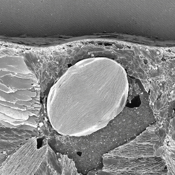
Achieving consistent FSW joint quality on die-cast aluminum requires tight control of four primary parameters:
| Parameter | Typical Range for Die-Cast Al Alloys | Effect of Variation |
|---|---|---|
| Tool rotation speed | 800–1,500 RPM | Too low: insufficient plastification, lack of bond. Too high: flash generation, tool wear |
| Traverse speed | 60–200 mm/min | Too low: overheating, softening. Too high: insufficient stirring, tunnel defect |
| Downward force (Z-axis) | 8–25 kN | Too low: void formation. Too high: tool fracture, excessive flash |
| Tool plunge depth | 0.1–0.3 mm below surface | Too shallow: root defect. Too deep: surface flash, tool damage |
Optimized parameters for ADC12 die-cast aluminum (based on published research):
- Tool rotation: 800 RPM
- Traverse speed: 60 mm/min (1.0 mm/s)
- Downward force: 12.3 kN
- Plunge depth: 0.1 mm
- Resulting joint tensile strength: 203 MPa (76% of parent material)
For AlSi10Mg die-cast, optimized parameters shift to higher traverse speeds due to the alloy’s better ductility:
- Tool rotation: 1,200 RPM
- Traverse speed: 150 mm/min (2.5 mm/s)
- Downward force: 15 kN
- Resulting joint tensile strength: 260 MPa (85% of parent material)
When NOT to Use FSW: Limitations and Alternatives
FSW is not a universal solution. It has specific limitations that make alternative methods preferable in certain scenarios:
Limitation 1: Joint Geometry Constraints
FSW requires access from one side with a flat or gently curved surface. Complex 3D geometries, internal cylindrical joints, or multi-axis seams are difficult or impossible. For internal tube-to-housing joints, electron beam welding or laser welding may be more suitable.
Limitation 2: Tool Access and Fixturing
The FSW tool requires a clear approach path and rigid fixturing to resist the 8–25 kN downward force. Small housings (<100 mm) may not provide sufficient flat surface area for effective clamping. In these cases, threaded plugs with O-ring seals or adhesive bonding may be more practical.
Limitation 3: Material Thickness Range
FSW is most effective for material thicknesses of 1.5–10 mm. Below 1.5 mm, the tool shoulder tends to thin the material excessively; above 10 mm, a single-pass weld requires very high forces and specialized tools. For very thick sections (>10 mm), narrow-gap MIG or electron beam welding may be preferred.
Limitation 4: Exit Hole
FSW leaves a "keyhole" at the end of the weld where the tool withdraws. This must be accounted for in the joint design — either by locating the exit hole in a non-critical area, using a retractable-pin tool, or filling the keyhole with a plug weld.
Limitation 5: Tool Cost for High-Silicon Alloys
FSW tools for welding ADC12 (high Si content) cost $500–2,000 per tool and last 200–500 m of weld length. For very high-volume production, this tool cost is justified by the <0.1% leak failure rate. For low-volume or prototype work, the tool cost may make MIG welding more economical despite higher reject rates.
Quality Assurance: How FSW Welds Are Verified
In IATF 16949-certified production, every FSW weld is verified through a combination of in-process monitoring and post-weld inspection:
| Inspection Method | What It Detects | Production Rate |
|---|---|---|
| Real-time force/torque monitoring | Tool wear, insufficient bond, voids | 100% (in-line) |
| Helium leak testing | Any through-thickness leak path | 100% (in-line) |
| X-ray radiography | Internal voids, tunnel defects, root defects | Sampling (1 per 50 parts) |
| Cross-section metallography | Weld nugget geometry, bond line integrity | PPAP + quarterly |
| Tensile testing (coupons) | Joint strength vs. parent material | PPAP + annual |
| Burst pressure testing | Coolant channel structural integrity | PPAP + annual |
Frequently Asked Questions
Q: Can FSW weld die-cast aluminum with existing porosity?
A: Yes. FSW is a solid-state process that operates below the melting point, so existing gas porosity in the die-cast parent material does not expand or create new defects. The tool’s downward force even partially closes existing pores at the joint surface. This is the primary reason FSW outperforms MIG/TIG welding on die-cast aluminum.
Q: What leak rate can FSW achieve on die-cast aluminum housings?
A: FSW routinely achieves helium leak rates below 1×10⁻³ mbar·L/s on die-cast aluminum housings, with production failure rates below 0.1%. For battery tray cooling plate applications, rates below 1×10⁻⁷ mbar·L/s are achievable. MIG and TIG welding typically achieve 8–15% failure rates on the same geometries.
Q: How long does an FSW tool last when welding ADC12 die casting?
A: For ADC12 (high Si content), tungsten-rhenium or PCBN tools last approximately 200–500 meters of weld length before requiring replacement. For AlSi10Mg, tool life extends to 500–1,000 meters. Tool wear is monitored via torque trend data, and replacement is scheduled before quality degradation occurs.
Q: Is FSW cost-effective compared to gasket sealing?
A: For high-volume production (>10,000 units/year), FSW is more cost-effective than gasket sealing over the product lifecycle. While the initial tooling and equipment investment is higher, the elimination of gasket replacement, leak-test rework, and field warranty claims reduces total cost of ownership by 30–50% over a 5-year production run.
Q: Can FSW be used on all die-cast aluminum alloys?
A: FSW can weld all common die-cast aluminum alloys (ADC12, A380, A360, AlSi10Mg, Castasil-37). However, alloys with higher silicon content (>10% Si) cause faster tool wear and may produce rougher surface finishes. AlSi10Mg and Castasil-37 offer the best combination of weld quality and tool life.


