

Last March we walked into a customer plant running a 2.8 kg ADC12 transmission housing on a 1,250-ton cell. Same die, same alloy, same shot profile as the October run. Scrap was 1.9% in autumn and 6.4% in March. The difference was 14 °C of shop-floor air and a cooling tower that had been cleaned over the winter.
On paper that plant had no thermal problem. The die ran at the temperature written on the process sheet. Which is the point of this article: the number on the sheet is an average, and the average hides the thing that costs money.
The die is never hot, and never even
A die surface reading 210 °C on a contact probe can swing 70–90 °C across the cavity. The probe goes where it is convenient to reach. The area that is soldering sits four centimetres away, at 295 °C, and nobody has measured it since the die was commissioned.
Aluminium carries roughly 0.9 kJ/(kg·K) of specific heat and gives up most of its latent heat inside the first 40 milliseconds of solidification. With a 70 mm gate and a 2.5 mm wall, the heat that arrives per shot is not evenly distributed: thick sections and the gate region load the die far harder than thin ribs near the overflow. A die is a heat exchanger with an irregular load map, and if the water circuits were designed to a rule of thumb — one circuit per 60 mm of die block, drilled straight — the map and the cooling do not match.
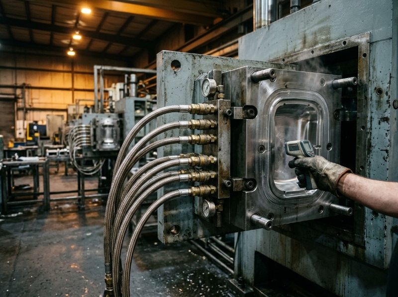
What you get is a permanent thermal gradient. The hot zone stays hot shot after shot because the water circuit there cannot pull the heat out fast enough, and the cold zone stays cold because it was over-cooled to compensate. Both produce scrap, and they produce different kinds: the hot zone solders, blisters and shrinks late; the cold zone cold-shuts, laps and misses fill at the far end of the cavity. When one operator chases both with a single die-temperature setpoint, the process oscillates for a week.
What a thermal map actually measures
Two numbers matter, and neither is the die temperature. The first is the peak surface temperature in the last-filled region at the moment the die opens. The second is how much that peak drifts over a production run — drift is what tells you whether the die is in balance or just not yet out of balance.
| Feature | Peak die surface, °C | Why | What goes wrong outside it |
|---|---|---|---|
| Gate and runner | 250–290 | Highest heat flux per shot; erosion plus thermal fatigue | Below 240: cold shut at gate. Above 300: washout and heat checking within 40k shots |
| Thick sections (≥6 mm) | 220–250 | Long solidification time, local shrinkage | Above 260: shrinkage porosity that only shows after machining |
| Thin ribs and fins (1.5–2 mm) | 200–230 | Fill finishes before the metal freezes | Below 190: lap lines; above 240: die soldering on the rib nose |
| Last-filled region | 190–220 | Has to stay liquid until the plunger stops | Below 180: incomplete fill at the far overflow |
| Slides and cores | 180–220 | Less mass, cools faster, moves | Cold core: pull marks and cracking at ejection |
These are the ranges we work to on ADC12 and A380 with wall thickness between 1.5 and 6 mm. A die running A380 at the top of every band is a die that will heat-check early. A die running everything at the bottom of the band is a die that will chase fill defects all night.
Summer is not a season, it is a 20 °C offset
The heat balance equation includes the room. A die loses heat to the air by convection and radiation, and that loss changes with ambient temperature, with the airflow from the extraction hood, and with how many other cells are running in the same bay. In a plant without climate control, the same die that balanced at 18 °C in October runs 15–20 °C hotter in a 36 °C August. The cooling water inlet temperature moves with it, because the tower is doing more work.
Three things follow, and they are the reason seasonal scrap is so common:
- The die needs less spray in summer, not more. Operators add release agent when parts stick, but sticking in a hot die is often a heat-extraction problem, and more spray adds a cool film that produces laps on the next shot.
- Cycle time creeps up in summer because the die cannot shed heat, and the natural fix — longer open time — makes the thermal gradient worse, not better, because the hot zone now has more time to be cooled by the same inadequate circuit.
- The drift shows up two hours into the shift, not at start-up. First-off inspection passes. The 400th part fails.
Any process sheet that specifies a die temperature without an ambient band is a sheet that will be violated every July. Ours carry the band: 200–230 °C at 20 ± 5 °C ambient, and a note that above 30 °C ambient the spray time drops by 15% and the cooling water setpoint goes down 2 °C.
The three levers that actually move the balance
Cooling circuit layout. A straight drilled circuit 25 mm from the cavity surface removes heat in a line, not in a map. Baffles and bubblers buy you maybe 20% more local extraction. Where the geometry allows it, a conformal insert printed in maraging or tool steel puts the channel 8–12 mm from the surface and follows the hot zone. A 2025 study in Engineering Failure Analysis on additively manufactured conformal cooling dies found the expected gain in thermal uniformity, and also the thing nobody puts in the sales deck: the printed insert becomes the life-limiting component of the tool, because the channel walls erode and the insert cannot be repaired the way a machined block can.
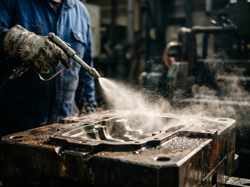
Spray. Release agent is a thermal tool that people use as a demoulding tool. Water-based lubricant removes 15–25% of the heat in a typical cycle, and the distribution matters more than the volume. Six seconds of spray aimed at the hot zone beats twelve seconds aimed at the whole cavity, and it does not build the film that causes paint adhesion problems downstream.
Cycle time. The relationship is not linear and it is not monotonic. Shortening the open time keeps the die hot; past a point it also keeps the part hot enough to warp when it is ejected. The correct question is not “what is the shortest cycle” but “at what open time does the last-filled region stop drifting”. That number is measurable, and it is usually 3–6 seconds longer than the number the production manager wants.
If you are chasing porosity rather than thermal stability, note that vacuum-assisted casting removes gas, not heat, and the two problems get confused on the floor constantly. A vacuum system that holds 80 mbar still produces shrink porosity if the hot zone is 30 °C too hot.
Where conformal cooling earns its money — and where it does not
We have quoted printed inserts on maybe a dozen tools in the last three years. They made sense on four: a 1.2 kg motor housing with a 9 mm boss that could not be cooled any other way, two structural parts where cycle time was the binding constraint, and one die where the hot zone sat directly behind a slide and a drilled circuit could not reach it.
They did not make sense on the rest. On a 400 g bracket with 2 mm walls, the die was already in balance and the printed insert added cost, a supply chain, and a repair procedure the customer’s toolroom had never run. Printed inserts also change how you think about die life: a machined H13 block can be welded and re-cut three or four times; a conformal insert with internal channels usually cannot.
The honest version: conformal cooling solves a heat-extraction problem that a better circuit design solves 70% of the time, for a fraction of the cost. Reach for it when the geometry, not the design, is the constraint.
A 40-minute check you can run this week
You do not need a thermal camera to find out whether the die is in balance, although one helps. What you need is repeatability.
- Run the die for 90 minutes at production settings. Do not touch anything.
- Every 15 minutes, measure the same six points with a contact probe: gate, two thick sections, the last-filled region, one slide, one core. Write the numbers down, in order.
- If any point moves more than 10 °C across the six readings, the die is not in balance. It is heating up or cooling down shot after shot, and the process will drift until it finds a new equilibrium — usually one that makes scrap.
- Measure inlet and outlet water temperature on each circuit. A ΔT above 8 °C means that circuit is doing more work than it was sized for; a ΔT below 2 °C means it is doing almost nothing, and the zone it passes through is being cooled by the die block instead.
- Compare the shape of the temperature map with the shape of the scrap. If the top three scrap locations are not the top three temperature deviations, the problem is not thermal and you should stop looking at the die.
That last point saves more money than any tooling upgrade. Roughly a third of the “thermal” problems we are called in for turn out to be gating, and a third turn out to be the alloy — a heat or a chemistry drift that the spectrometer caught but nobody read. Thermal growth also has to be allowed for in the tool: a 300 mm aluminium casting at 200 °C die temperature is not the same size as the drawing, which is why tight tolerance work starts with the thermal model, not with the machining strategy.
| What you see | What the thermal map usually shows | First action |
|---|---|---|
| Soldering on a boss or rib | Local peak above 280 °C, no circuit within 30 mm | Add a bubbler or baffle; do not add release agent |
| Cold shut at the far end | Last-filled region below 190 °C | Reduce cooling there, lengthen fill time 5% |
| Shrink porosity after machining | Thick section 20–30 °C above its band | Cool the section, or accept and add a squeeze pin |
| Scrap rising two hours into the shift | Drift, not offset | Check water ΔT and spray timing before touching the shot profile |
| Die cracking at 60k shots | Peak temperature cycling 150 °C or more per shot | Raise the low point of the cycle, not the high point |
Before the steel is cut, thermal simulation is cheap and worth doing — we run it on every new tool, and it changes the circuit layout maybe half the time (what moldflow catches before you cut steel). After the steel is cut, every thermal fix costs ten times more, which is the same arithmetic that makes scrap the most expensive line item in a die casting project that nobody budgeted for.
Frequently Asked Questions
What die temperature should we run for ADC12?
There is no single number. For 1.5–6 mm walls we work to 200–250 °C peak surface depending on the feature, with the gate hottest and the last-filled region coolest. What matters more than the setpoint is the spread: if two points on the same die differ by more than 40 °C, the die is not in balance regardless of the average.
Why does our scrap rate rise in summer?
Because the die sheds less heat to a hotter room and receives warmer cooling water, so the same settings produce a different thermal state. The usual symptom is drift two to four hours into the shift, not a bad first-off. Add an ambient band to the process sheet and reduce spray time as ambient rises.
Do we need conformal cooling inserts?
Only if a hot zone cannot be reached by a drilled circuit, or if cycle time is the binding constraint on a part with thick sections. On most tools a better circuit layout, a baffle and a corrected spray pattern get 70% of the benefit for a fraction of the cost.
How do we measure die thermal balance without a thermal camera?
Six fixed points, measured every 15 minutes for 90 minutes. If any point drifts more than 10 °C across the run, the die is not in balance. A camera makes the diagnosis faster and more convincing to management, but it does not find anything the six-point check misses.
Thermal balance is unglamorous work. It does not produce a new machine or a new alloy, and the fix is usually a machining change to a water circuit that was drawn in 2019. But it is the difference between a die that runs at 2% scrap for 120,000 shots and one that runs at 5% and gets blamed on the alloy.


