

Liquid aluminum injected at 5 meters per second under 1,000 bars of pressure does not care about the symmetry of your CAD model. High-pressure die casting (HPDC) is a violent, highly volatile thermodynamic event. If you rely on trial and error on the foundry floor to dial in your casting parameters, you are already too late.
Modifying hardened H13 tool steel because of unforeseen shrinkage or air entrapment costs tens of thousands of dollars and pushes T1 sample deliveries back by weeks. For Tier 1 and Tier 2 suppliers operating under strict IATF 16949 quality systems1, this level of supply chain risk is unacceptable.
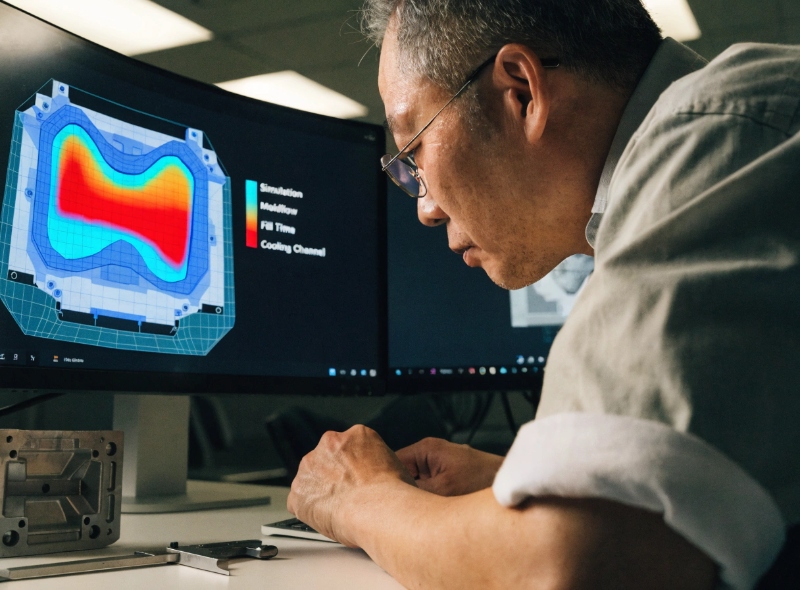
The only pragmatic way to mitigate these physical realities is through predictive engineering. Here is an inside look from the foundry floor at how we use Moldflow simulation to eliminate—or strategically relocate—automotive die casting2 defects before a single chip of steel is cut.
The Original Insight: We Don’t Eliminate Porosity, We Move It
Let’s dispense with the marketing fiction: there is no such thing as an "absolutely zero-porosity" die casting. The physics of metallurgical shrinkage and high-speed injection mean that micro-voids will always exist.
The true purpose of Moldflow simulation isn’t to magically erase porosity; it is to control exactly where that porosity ends up.
If a designer places a thick mounting boss next to a 1.5mm thin wall, that boss will cool last, acting as a magnet for shrinkage voids. If secondary CNC operations machine an O-ring groove right through that boss, the hidden porosity is exposed, and the housing will fail leak testing. Through simulation, we can optimize the gating and runner designs to push that trapped gas and shrinkage into external overflow wells (which are later trimmed off) or into non-critical, unmachined structural areas.
Defect Matrix: What Moldflow Actually Fixes
Here is a breakdown of the most common die casting defects and how thermodynamic simulation neutralizes them.
| Casting Defect | Root Cause in the HPDC Process | The Moldflow Simulation Fix |
|---|---|---|
| Gas Porosity (Blisters) | Air trapped inside the cavity by turbulent metal flow. | Optimizes gate speeds to ensure a laminar flow front. Dictates the exact timing for Vacuum HPDC triggers. |
| Shrinkage Porosity | Thick sections cool slower than thin sections, shrinking without fresh metal to feed them. | Identifies thermal "hot spots." Guides the placement of conformal cooling channels and chilling pins. |
| Cold Shuts (Flow Marks) | Metal cools and solidifies before two flow fronts merge together. | Simulates temperature drops. Allows engineers to adjust wall thickness or add overflow wells to draw hot metal through the cold zone. |
| Galling / Soldering | Insufficient draft angles or localized overheating causing aluminum to weld to the die steel. | Maps temperature distribution on the die surface to optimize the spray of water-based release agents. |
1. Combating Cold Shuts in Large-Format Castings
As the industry shifts toward large-format structural components like EV battery trays3, the distance the molten aluminum must travel increases dramatically.
If the metal loses too much temperature before reaching the extremities of the mold, the flow fronts will meet but fail to fuse completely. This creates a "cold shut"—a severe structural weakness that will snap under dynamic chassis loads. Moldflow allows our tooling engineers to visualize the exact temperature of the flow front in real-time. If we see the temperature dropping below the critical threshold (e.g., for AlSi10MnMg), we can redesign the runner system to feed metal faster or increase the local die temperature to ensure a homogenous, high-yield-strength fusion.
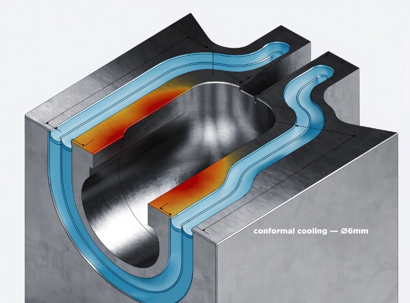
2. Preventing Thermal Warpage via Conformal Cooling
Die casting molds are essentially giant heat exchangers. If one side of a transmission case cools faster than the other, the residual internal stresses will cause the aluminum to warp the moment it is ejected from the die.
When dealing with large sealing flanges, even a 0.5mm warpage will prevent the CNC fixture from clamping the part evenly, ultimately destroying the final coplanarity of the mating face. Moldflow simulation maps the exact heat distribution across the H13 steel. We use this data to drill precision "conformal cooling" water lines that wrap around the specific geometry of the part, forcing a uniform cooling rate and preventing thermal distortion.
3. Optimizing the PQ2 Diagram
The relationship between pressure (P) and flow rate (Q) is known as the PQ2 diagram, and it is the mathematical heartbeat of the die casting machine.
If the plunger injects the metal too slowly, you get cold shuts. If it injects too violently, the metal atomizes, trapping massive amounts of air and destroying the tool. Moldflow software calculates the exact gate area, fill time, and intensification pressure required for a specific alloy. We take these simulated parameters and program them directly into the PLC of our casting cells, ensuring that the first shot is backed by hard math, not operator guesswork.
Secure Your Design Before Cutting Steel
At EMP Tech, we know that surviving strict OEM audits requires a foundation built on objective data. You cannot inspect quality into a part that was designed with fundamental thermal flaws. Our quality control and inspection4 begins in the digital realm.
By strictly adhering to NADCA engineering guidelines5 and running relentless DFM simulations, we help Tier 1 and Tier 2 integrators mitigate risk, prevent tooling delays, and ensure their components are truly assembly-ready.
Are you developing a complex thermal or structural component?
Upload your 3D CAD (STEP/IGES) through our contact form today. Our engineering team will run a preliminary DFM review, highlight potential shrinkage risks, and deliver a pragmatic manufacturing quote within 24 hours.
References & Footnotes
International Automotive Task Force. IATF 16949:2016 Quality Management System Requirements. ↩
EMP Tech. Automotive Aluminum Die Casting Solutions. ↩
EMP Tech. EV Battery Case (Tray) Manufacturing Capabilities. ↩
EMP Tech. Automotive-Grade Quality Control & Inspection Lab. ↩
North American Die Casting Association (NADCA). Engineering & Design Standards. ↩


