

In 2026 a single AI rack stopped being an air-cooling problem. Lenovo’s product guide for the NVIDIA GB300 NVL72 puts the rack at 135 kW TDP, up to 155 kW at peak, and splits heat capture roughly 90% to liquid and 10% to air. NVIDIA’s Vera Rubin generation goes further, running 45°C warm-water loops so an operator can fit up to 10% more NVL72 racks inside the same power budget. Manufacturing guidance published this year traces the same curve from the other direction: rack density has moved from 8–15 kW to 40–130 kW in about three years.
Every one of those racks needs cold plates, manifolds, hoses, quick disconnects and a coolant distribution unit. Buyers then ask their die caster the obvious question: can you cast the cold plate? For most cold plates the honest answer is no. For the parts around them it is often yes, and that distinction is where projects get into trouble. We build industrial die castings for exactly this kind of envelope, and the first thing we do on a liquid cooling RFQ is separate the wetted pressure boundary from the structural hardware.
A Cold Plate Is Not a Die Casting
A cold plate is a liquid-to-solid heat exchanger mounted directly on a die or package, with coolant pumped through internal channels. Its performance is set by two independent decisions: how the fins are formed, and how the plate is closed into a pressure boundary.
That definition matters, because "cold plate" and "die casting" are usually not the same conversation. Fin forming is done by skiving, CNC milling, extrusion or brazed foil stock. Closure is done by vacuum brazing, friction stir welding, fusion welding or an O-ring gasket. Die casting appears in neither list.
| Fin method | Fin thickness | Fin pitch | Typical volume breakpoint |
|---|---|---|---|
| Skiving | 0.2–0.6 mm | 0.3–1.2 mm | 500–50,000/yr |
| CNC milled channels | 0.8 mm min | 1.5 mm and up | under 500/yr |
| Extrusion | 0.5–0.8 mm | 1.5–3.0 mm | 10,000/yr and up |
| Brazed foil stock | 0.1–0.2 mm | 0.5–2.0 mm | 5,000/yr and up |
The numbers explain the boundary. High-pressure die casting cannot reliably fill a 0.5 mm fin at 1 mm pitch — the alloy freezes before the cavity fills, and you get a cold shut instead of a heat sink. If someone offers to die cast a fin field for a 700 W GPU, ask for thermal test data rather than a price. Above roughly 100 W/cm² the fin-to-base joint dominates performance and skiving wins; below about 60 W/cm², fin density matters more and brazed stock becomes attractive. Nowhere in that range does a cast fin field compete.
Where die casting belongs is the plumbing around the plate.
Where Die Casting Actually Fits
A liquid-cooled rack is a small fluid plant. It has a supply manifold, a return manifold, a CDU with pumps and a heat exchanger, drip trays, brackets, and a lot of mounting hardware. Several of those are natural castings.
| Part | Why casting fits | What has to be machined after |
|---|---|---|
| Rack supply/return manifold | 3D internal routing, integrated ports and mounting bosses | O-ring grooves, port threads, mounting face |
| CDU housing / pump housing | complex internal volume, structural stiffness | bearing bore, sealing lands, flange faces |
| Reservoir / expansion tank | free-form volume, low pressure | filler neck, level sensor boss |
| QD mounting plate | many ports in one datum, tight position tolerance | port bores, flatness |
| Drip tray, fan frame, brackets | non-wetted structure, cost per unit | usually little or none |
The split that matters is wetted versus non-wetted. A bracket or a fan frame can use A380 and be judged on cost and stiffness. A manifold or a pump housing is a pressure boundary, and the rules change completely.
Why a Cast Manifold Beats a Machined Block at Volume
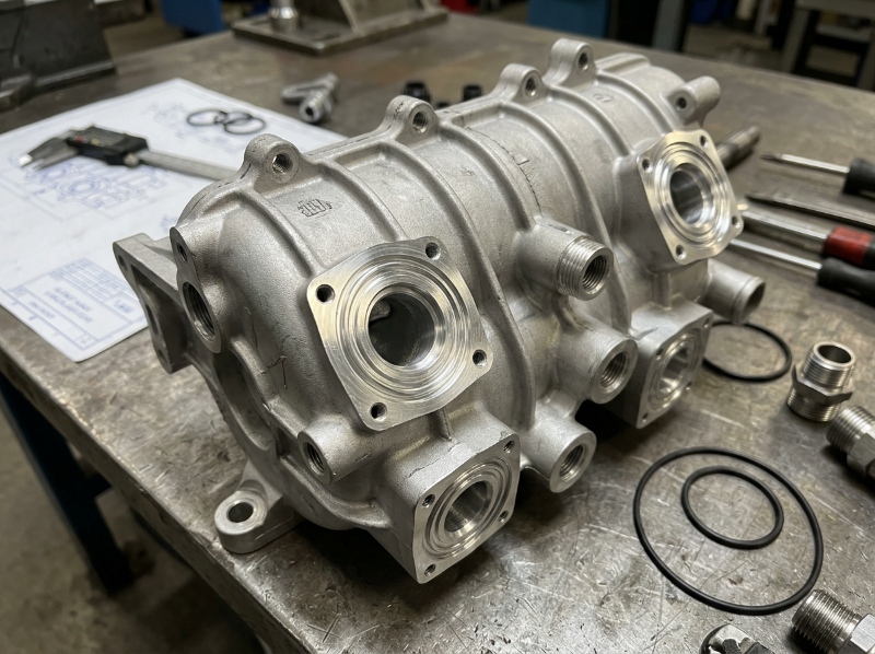
A manifold that routes coolant from a rack supply line to eighteen cold plates is a genuinely three-dimensional part. Machined from billet, you pay for every kilogram you remove, and internal turns are painful — either multiple setups, or a split-and-bolted design with twice the leak paths. Casting produces the external shape and the internal volume in one shot, then you machine only the interfaces: O-ring grooves, port threads, mounting faces.
On a part that starts as a 6 kg block and ships at 1.8 kg, the material saving is visible on the quote before anyone discusses cycle time. Add the machining hours you no longer spend hogging out an internal cavity, and the case is usually clear.
The caveat is the one that sinks programs: casting gives you the shape, not the pressure boundary. A die-cast manifold still needs a cover closed by FSW, brazing or a gasket, and those sealing faces still need machining. A quote for a "ready to use" cast manifold with no closure step is a quote for a part that will weep in the test cell.
The Leak Path You Cannot See
Porosity in a die casting is not automatically a defect. In a structural bracket it is often irrelevant. In a pressure boundary it is the whole game, and the failure mode is ugly because it shows up after machining.
We had a manifold program where T1 parts passed X-ray as cast, then failed helium at the sealing boss after machining. The porosity had been there all along, about 1.2 mm under the as-cast skin — inside the zone the cutter removed to form the O-ring groove. Nothing was wrong with the casting inspection. The inspection simply happened before the cut.
The fix was not a tighter X-ray acceptance number. It was moving the gate and the overflow so the last-filled metal sat away from the sealing bosses, then specifying enough machining stock that the groove landed below the shrinkage zone. Two tool iterations. The second one held.
What we now write into every wetted RFQ:
- Gates and overflows stay away from sealing faces, threaded ports and weld lands.
- Minimum machining stock is specified per face, not left to the shop.
- Vacuum-assisted casting is standard on pressure-tight parts — the same VHPDC reasoning we use on EV housings.
- X-ray is performed as cast and again after machining on the sealing faces.
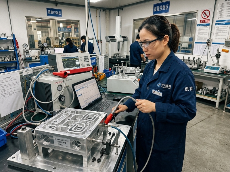
- Every part gets a 100% helium or pressure-decay test, not a sample.
- Threads that will be serviced go into steel inserts or helicoils, never directly into the casting.
That list is the difference between a manifold that holds 1.5 bar and one that holds 20. It is also ordinary quality control discipline, applied to a fluid boundary instead of a dimensional one.
Pressure: What the Loop Actually Demands
IEC 62368-1 requires leak testing at three times normal operating pressure, and twice the pressure under single-fault conditions. Design the loop at 450 kPa and the test is planned around 1,350 kPa. Normal service pressure is not the number that sizes your wall; the proof test is.
Closure method sets the ceiling, and it should be chosen before wall thickness:
| Closure | Typical pressure rating | Distortion | Serviceable |
|---|---|---|---|
| Vacuum brazing | 10–20 bar | high, full furnace cycle | no |
| Friction stir welding | 20–40 bar | low, localized heat | no |
| Fusion welding | 10–25 bar | moderate to high | no |
| O-ring gasket | 5–10 bar | none | yes |
A die-cast manifold with an FSW cover sits at the top of that table. A gasketed design belongs on serviceable, lower-pressure runs. Neither choice is a casting decision, which is precisely why the casting supplier and the joining supplier need to be in the same conversation before the drawing is frozen.
On section: pressure-tight castings usually want 2.5–3.5 mm walls. That is thicker than the 1.5 mm you would specify on a structural housing, and it is not laziness. Thin walls are for mass; pressure boundaries are for section. Isolated heavy bosses next to thin walls create shrinkage porosity exactly where you cannot afford it, so transition gradually and put generous fillets at every internal corner.
Coolant Chemistry Changes the Alloy
Most single-phase AI loops run inhibited 50/50 propylene or ethylene glycol, held at pH 7–9 with chloride below 25 ppm. Two implications land directly on the casting specification.
The first is copper. A380 carries roughly 3–4% copper and ADC12 about 1.5–3%. In a wetted aluminium loop that copper is a corrosion risk and a galvanic partner waiting to happen. For wetted parts we default to a low-copper AlSi10MnMg, which is less forgiving to cast than A380 but far safer in glycol. For non-wetted brackets, use A380 and stop overthinking it.
The second is the wetted circuit as a whole. A brass fitting or a stainless QD threaded into an aluminium manifold creates a galvanic couple, and the anode is your casting. Specify fitting material and the isolation method on the drawing, not in a email after the first leak.
One more thing that gets skipped: glycol is not a cleaning agent. Casting residue, machining coolant and core sand left inside a manifold will end up in the pump. Cleanliness to a written standard is a reliability requirement here, not an automotive ritual. If heat paths and coolant chemistry are the constraint, our notes on high thermal conductivity die cast housings cover the material side.
Flatness and the Machining Sequence
A cold plate mounting face typically needs 0.025 mm flatness across the die footprint. A raw die casting is nowhere near that, so the face is machined. But a part with heavy bosses on one side and a thin cover flange on the other will move after machining unless residual stress is dealt with first.
Put the sequence on the drawing: cast → stress relieve → machine datums → machine sealing faces and mounting face → leak test. Suppliers who machine first and stress-relieve later will deliver parts that were flat on the CMM and are not flat in the rack. We have seen that movie.
Where Die Casting Loses
Worth saying plainly, because a supplier who claims everything should be cast is telling you something about the supplier.
- High heat flux. Above roughly 100 W/cm², the fin-to-base interface dominates and skiving wins. Casting cannot produce that interface.
- Fine fin pitch. 0.3–1.2 mm pitch is skiving territory. HPDC minimum practical wall is an order of magnitude coarser.
- Copper cold plates. Copper’s thermal conductivity is why high-flux plates use it. Aluminium die casting is the wrong material conversation.
- Low volume. A pressure-tight manifold tool is a real investment. Below a volume that amortises it — the number moves with part size and how much machining the casting removes, but in our experience it is a few thousand units a year for a fist-sized body — billet or fabricated exists for a reason.
- Very large flat plates. Extrusion beats casting on cost per unit area, and the straightness problem is solved by machining after straightening.
What to Put in the RFQ
- Wetted or non-wetted, stated per part number.
- Alloy and temper, written out — "AlSi10MnMg, as-cast" or "A380, no T6".
- Design pressure, proof-test pressure and the standard you are testing to.
- Closure method and who owns the joint.
- Sealing faces and O-ring grooves, called out individually, with machining stock.
- Coolant chemistry — glycol type, concentration, pH and chloride limits.
- Cleanliness standard and the test method.
- Leak-test method and acceptance rate, with the test performed after machining.
Most of the avoidable failures we see start with items 1 and 5 being left to the supplier’s imagination.
The 2026 Supply Chain Reality
The AI buildout has pulled liquid cooling from a niche into a volume program in about two years, and the supply base is still catching up. Manifold and CDU capacity is being booked alongside the rack programs, OCP’s cold plate and rack specifications are setting the test language buyers use, and lead times for pressure-capable tooling are stretching.
Three practical consequences for a buyer. First, ask for the leak-test data before the price — a cheap manifold that fails helium at 2 bar is not cheap. Second, dual-sourcing a cast manifold means funding two tools or accepting one; decide which. Third, if the rack ships into the EU, the aluminium in these parts now carries carbon reporting obligations, so the material declaration conversation starts earlier than it used to.
Where We Sit
We cast structural and pressure-tight aluminium parts on 13 high-pressure cells from 350T to 3050T, VHPDC standard, with 150-plus 4- and 5-axis CNC stations for the post-cast machining a manifold needs. Zeiss CMM, X-ray NDT and 100% in-line helium or air decay testing are already in the flow, under IATF 16949 and VDA 6.3 "A" systems. Coolant manifolds and CDU housings are a natural extension of that work, not a new capability we are inventing for the pitch.
What we do not do is skive fin fields or braze cold plate stacks. If that is the part you need, we will say so on the first call. If you need the manifold, the pump housing or the mounting plate that makes the loop work, send the drawing, the design pressure and the annual volume.
Frequently Asked Questions
Q: Can cold plates be made by aluminium die casting?
A: The fin field usually cannot. Cold plate fins are formed by skiving, CNC milling, extrusion or brazed foil at pitches and thicknesses die casting cannot fill. Die casting is used for the surrounding plumbing — manifolds, CDU and pump housings, mounting plates.
Q: What pressure must a die-cast liquid cooling manifold hold?
A: It depends on the loop, but IEC 62368-1 requires leak testing at three times normal operating pressure and twice the pressure under single-fault conditions. A 450 kPa design therefore needs proof testing around 1,350 kPa, which drives wall thickness and closure choice.
Q: Why do die-cast manifolds leak after machining?
A: Shrinkage porosity often sits a millimetre or two below the as-cast skin. Machining an O-ring groove can open it, creating a leak path that passed X-ray before the cut. Gate and overflow placement away from sealing bosses, plus specified machining stock, is the standard fix.
Q: Which aluminium alloy should be used for a glycol-cooled manifold?
A: A low-copper alloy such as AlSi10MnMg is the safer default for wetted parts, because A380 and ADC12 contain copper that raises corrosion risk in glycol loops. Non-wetted brackets can use A380 on cost and castability.
Q: Is die casting cheaper than machining for data center coolant manifolds?
A: At volume it usually is, because the internal routing and mounting bosses come out of the tool rather than the cutter, and far less metal is removed. Below the volume that amortises a pressure-capable tool, billet or fabricated manifolds remain the sensible route.


