Your parts don’t fit together during assembly or fail critical leak tests1. This is a frustrating problem often caused by a misunderstanding of what dimensional tolerances2 are achievable in die casting.
The aluminum die casting tolerance standard3 is a set of guidelines, like ISO 8062-34 or NADCA standards5, that define the achievable dimensional accuracy for cast parts. They provide a common language between designers and manufacturers to prevent costly errors and ensure proper part function.
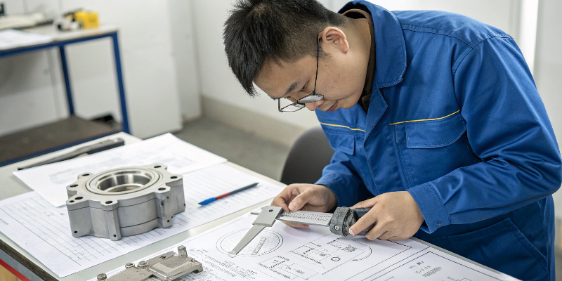
When I talk with a new client, one of the first things we review on their drawing is the title block, specifically the tolerance callouts6. This tells me a lot about their expectations. In my 20 years of experience, the root cause of many production issues can be traced back to unrealistic or poorly defined tolerances. Setting clear, achievable standards from the very beginning is not just "good engineering." It’s the foundation for a successful, high-volume manufacturing project. Let’s look at how these standards work in the real world.
What Are Tolerances in Aluminum Die Casting and Why Do They Matter?
You’ve approved a design, but the parts that arrive don’t fit together correctly. This can cause major delays on your assembly line, costing your company time and money.
A tolerance is the acceptable range of variation7 for a specific dimension of a part. Tolerances are critical because they guarantee that parts will fit, function, and seal correctly every single time, even when they’re made in different batches.
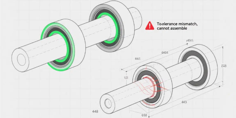
Tolerances are the language of precision. When a drawing says a part is 100 mm long, it’s never exactly 100.0000 mm. The tolerance tells us how much it’s allowed to vary. For example, a note like "100 mm ±0.2 mm" means any part measuring between 99.8 mm and 102.2 mm is acceptable. This matters enormously. For a complex EV inverter housing, the flatness tolerance8 of the main sealing surface might be just 0.2 mm over its entire length. If the part warps by 0.3 mm, the gasket won’t seal, and the multi-million dollar electronics inside will be destroyed by water ingress. The tighter the tolerance, the more care, control, and often cost is required to achieve it. So, a key part of my job is to help customers find the right balance between the precision they absolutely need and what is practical to manufacture.
What Are the ISO 8062 and NADCA Tolerance Standards?
You’re working with suppliers globally, and "tight tolerance" means something different in every factory. This confusion leads to quotes being all over the map and parts that don’t meet your real needs.
ISO 8062 and the NADCA Product Specification Standards are internationally recognized guidelines. They create a standardized system, or a common language, for defining casting tolerances9 based on the part’s size, complexity, and the process used.
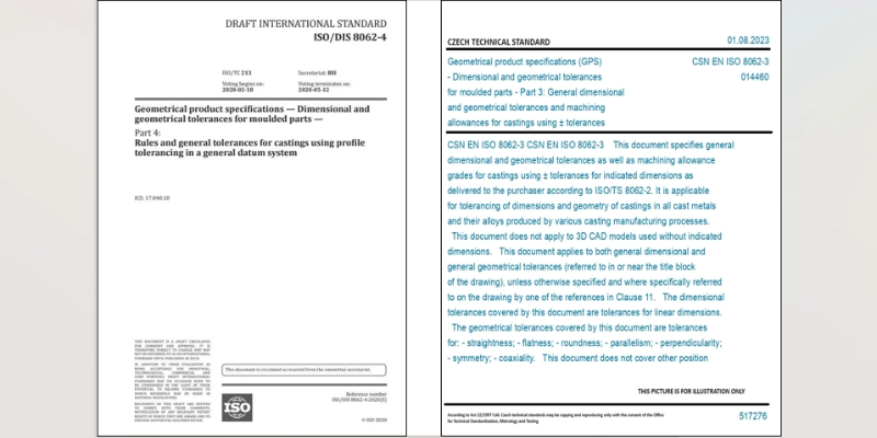
These standards save us from endless arguments about what is "good enough." Instead of using vague terms, we can refer to a specific grade. For example, the ISO 8062-3 standard provides different "Casting Tolerance" grades, or CT grades. A simpler part might be acceptable at grade CT6, while a more precise part might require a CT5 grade. The NADCA (North American Die Casting Association) standards are very similar and are widely used in the US, Canada, and Mexico. They provide clear tables for everything from linear dimensions and flatness to draft requirements. When we kick off a project at EMP Tech, we agree with the customer on which standard and which grade to follow. This creates a clear and objective contract. It means that a Supplier Quality Engineer10 quality auditor can audit us against a globally recognized benchmark, not just an opinion.
| Standard Feature | ISO 8062-3 | NADCA Standards |
|---|---|---|
| Primary System | Uses "CT" grades (e.g., CT4-CT8 for HPDC). | Uses "Precision" and "Standard" categories. |
| Scope | Covers all casting processes (sand, investment, die). | Specifically focused on die casting. |
| Application | Widely used in Europe and Asia. | Primary standard in North America. |
| Core Concept | Tolerance value increases with nominal dimension. | Tolerance value increases with nominal dimension. |
How Does Part Geometry Affect Achievable Tolerances?
You have designed a complex part with many features, and your supplier is struggling to hold the tolerances. They say the part’s shape itself is the problem, which is a frustrating answer.
The shape of the part has a massive impact on tolerance. Long, unsupported sections are prone to warping, affecting flatness. Features formed by two moving halves of the mold will always have a looser tolerance than features formed within one solid piece of steel.
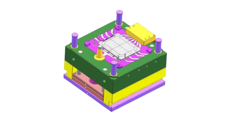
This is one of the most important lessons I’ve learned on the shop floor. A casting is not a perfectly rigid object when it’s made; it’s a semi-solid material cooling from 660°C. Its geometry will dictate how it behaves. The biggest factor is the parting line11, the seam where the two halves of the mold meet. Any dimension that crosses this line will have added variation from the mold’s alignment, wear, and thermal expansion12. For a large motor housing, a dimension within one mold half might hold a ±0.15mm tolerance. But the overall length of the part, which crosses the parting line, might only be able to hold ±0.4mm. Another factor is wall thickness. If a designer puts a very thick section next to a very thin wall, it will cool unevenly. The thick section will shrink more, pulling on the thin section and causing the entire part to warp, making it impossible to hold a tight flatness tolerance without expensive post-machining.
What’s the Difference Between Machining Allowances and As-Cast Tolerances?
Your supplier’s quote has separate costs for casting and machining, and you’re not sure why both are needed. You need to understand where to use as-cast tolerances versus where to pay for CNC machining13.
"As-cast" tolerance is the precision of the part straight out of the mold. It’s cost-effective but less precise. For critical areas, we add extra material ("machining allowance14") so a CNC machine can cut it to a much tighter "machined tolerance."
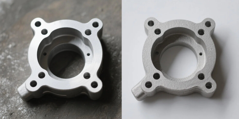
This is a critical discussion I have with every Purchasing Director. The choice between as-cast and machined surfaces directly impacts the final part cost and performance. The "as-cast" part is the most economical form, but it’s subject to the natural variations of the casting process. For many features, like the outer shape or reinforcing ribs, this is perfectly fine. But for features that need to be extremely precise—like the flat surface where a lid seals with a gasket, the round bore where a bearing will be pressed in, or the threaded holes for assembly—as-cast is not good enough. For these areas, we intentionally design the casting with extra metal, typically about 0.5 mm to 1.0 mm. This is the machining allowance. After casting, we put the part into a CNC machine, which then cuts this extra material away to produce a perfectly flat, round, or precisely located feature with a tolerance that can be ten times tighter than what the casting process alone can hold.
How Do You Design for Manufacturability Within Tolerance Standards?
You want to avoid the endless cycle of design revisions. Designing a part that is inherently easy to manufacture within standard tolerances from the beginning saves huge amounts of time and money.
Design for Manufacturability (DFM) means creating a design that is naturally stable and easy to cast. The key principles are using uniform wall thickness15, generous draft angles16, and simple, robust geometry wherever possible to minimize stress and warpage.
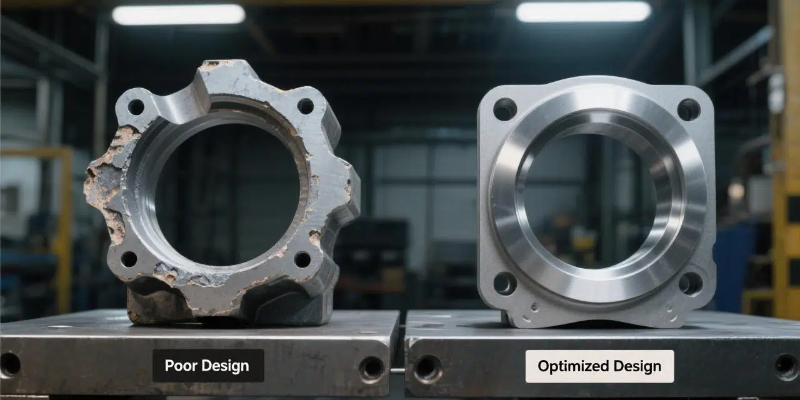
The best way to control tolerances is to design the part smartly from day one. I’ve seen brilliant product designs that were nearly impossible to manufacture because they ignored a few basic DFM rules. When my team and I consult with customers, we focus on a few key areas to ensure their parts are robust and stay within tolerance.
- Uniform Wall Thickness: This is the golden rule. It helps the part cool evenly, which is the single best way to prevent internal stress and warpage.
- Generous Draft Angles: Every vertical wall of the part needs a slight angle, or "draft," so it can be pushed out of the mold without being damaged or distorted.
- Fillets and Radii: Sharp internal corners create stress and can cause cracks. Smooth, rounded corners help the metal flow nicely and create a stronger part that is less likely to distort.
- Clear Datums: The engineering drawing17 must clearly define the three reference planes (datums) from which all critical dimensions are measured. This ensures that when we inspect the part on our CMM machine, we are measuring it the exact same way the customer will.
Conclusion
Understanding and applying tolerance standards like ISO 8062 is not just a technical detail. It is essential for ensuring part quality, managing costs, and achieving the reliable performance demanded by modern industries.
-
Understanding critical leak tests is essential for ensuring part reliability and performance. ↩
-
Understanding dimensional tolerances is crucial for ensuring parts fit and function correctly. ↩
-
Explore this resource to understand the guidelines that ensure dimensional accuracy in die casting. ↩
-
Learn about ISO 8062-3 to grasp the international guidelines for casting tolerances. ↩
-
Discover NADCA standards to understand the benchmarks for die casting in North America. ↩
-
Explore tolerance callouts to learn how they communicate expectations in part design. ↩
-
Learn about acceptable ranges to ensure parts meet functional requirements. ↩
-
Understanding flatness tolerance is key to ensuring proper sealing and part function. ↩
-
Explore casting tolerances to understand their role in achieving quality in die casting. ↩
-
Understanding the role of a Supplier Quality Engineer can enhance quality assurance in manufacturing. ↩
-
Learn about the parting line to understand its impact on dimensional accuracy. ↩
-
Explore the effects of thermal expansion on casting processes and tolerances. ↩
-
Explore CNC machining to see how it enhances precision in part manufacturing. ↩
-
Learn about machining allowance to understand how it impacts part precision and cost. ↩
-
Learn why uniform wall thickness is crucial for preventing warpage in cast parts. ↩
-
Explore the importance of draft angles for easy mold release and part integrity. ↩
-
Explore the significance of engineering drawings in communicating design specifications. ↩


