Your EV components keep failing air leakage tests, delaying projects and creating tension. Finding the root cause is a frustrating hunt, often ending in a blame game between departments.
The most common reasons for air leakage in aluminum die casting1s are gas porosity2, cold shuts3, cracks, machining damage4, poor flatness5, bad mold venting6, and improper handling. The root cause is rarely a single issue but a combination of factors across the entire manufacturing process.

Solving air leakage is one of the biggest challenges in producing high-performance parts like motor controller housings or battery enclosures. A leak that seems to appear in final testing often has its roots much earlier, sometimes even in the initial part design. Blaming the die casting machine operator or the CNC machinist is an easy way out, but it rarely solves the problem for good. The only way to guarantee airtight components is to look at every single step, from the digital design file to the final packaging. I’ve spent over 20 years tracking down these issues, and it always comes down to full-process quality control. Let’s break down the seven most common culprits I see in the field.
How does entrapped air during injection cause gas porosity?
You see tiny, pinhead-sized bubbles on a machined surface. The raw casting looked fine, but after machining, it fails the pressure test7. You correctly suspect porosity is the issue.
Gas porosity forms when air gets trapped in the molten aluminum during the high-speed injection phase. These air bubbles become permanent voids inside the casting. While they may be sealed under the surface, machining can expose them, creating a direct path for air to leak.
The injection process is a violent event. We are forcing liquid metal into a steel mold in milliseconds. If the flow is too turbulent, it folds over on itself and traps air. Think of it like pouring a drink too fast—you get a lot of foam. In die casting, that "foam" is trapped gas. The key is to manage the speed of the plunger that pushes the metal. We have a slow shot phase to let the metal fill the runner system smoothly, then a fast shot phase to fill the part cavity quickly before it freezes. If that transition from slow to fast is in the wrong place or at the wrong speed, you will trap air. I remember a motor controller housing project for a German client that had persistent leaks. We used mold flow simulation8 to analyze the filling pattern. The simulation showed that air was being compressed and trapped in a corner pocket. By adjusting the shot profile and adding a small overflow well in that area, we gave the trapped air a place to go. This simple process adjustment eliminated the porosity and solved the leakage issue permanently.
Can poor metal flow lead to cold shut defects and leaks?
You notice a fine, hairline crack on the surface of your casting. It might seem like just a cosmetic flaw, but the part consistently fails the leak test in that exact area.
A cold shut is not a crack; it’s a line where two fronts of molten metal failed to fuse together properly. This happens when the metal cools too much before merging, creating a continuous leak path right through the casting wall. It is a fundamental failure of fusion.
For the two metal flows to fuse into one solid piece, they need to be hot enough and meet with enough pressure. If they are too cold, they will just press against each other, leaving a permanent boundary. The main causes are straightforward: the metal temperature is too low, the mold temperature is too low, or the injection speed is too slow. I was at a customer’s plant in Canada helping them with an on-board charger (OBC) housing. They had terrible cold shut issues near a thin-walled section far from the gate. Their mold temperature was set uniformly, but that thin area was losing heat too fast. We helped them install dedicated heating cartridges in that specific section of the mold. Raising the local die temperature by just 30°C kept the metal fluid long enough for the two fronts to merge perfectly. This shows that a one-size-fits-all process setting doesn’t work for complex parts. You have to manage temperature and flow in every zone of the part.
| Factor | The Problem | The Solution |
|---|---|---|
| Metal Temperature | Too low to stay fluid during filling. | Increase holding furnace temperature; reduce transfer time. |
| Mold Temperature | Too low, chilling the metal too quickly. | Increase overall mold temp; add local heating channels. |
| Injection Speed | Too slow, giving metal time to cool. | Increase fast shot speed; optimize shot profile. |
The part looks perfect coming out of the machine. It even passes an initial visual check. But after cooling down completely, or after machining, tiny cracks appear and cause leaks.
Yes, cracks are often caused by stress. Thermal stress happens when thick and thin sections of the casting cool at different rates, pulling the part apart. Ejection stress happens when the part is pushed out of the mold with too much force, causing it to fracture.
Aluminum shrinks as it cools. If you have a part with a thick boss right next to a thin wall, the thin wall will solidify and shrink first. The thick boss, still hot and weak, gets pulled by the shrinking thin wall, creating a tear. We call this a "hot tear," and it’s a common source of leaks. The solution here often lies in the part design itself. For a structural component we developed, we saw micro-cracks forming near a large, solid boss. Our DFM analysis showed a massive difference in cooling times between the boss and the adjacent walls. We worked with the customer’s design team to core out the boss, making its wall thickness more uniform with the rest of the part. We also added generous radii at the intersection. These design changes distributed the stress evenly and eliminated the hot tears. Ejection cracks are more mechanical. If the part design has insufficient draft angles (taper), or if the mold surface is rough, the part will stick. When the ejector pins push, they apply concentrated force and can easily crack the casting. Regular mold maintenance and proper part design are essential to avoid this.
Could your CNC machining process be creating surface leaks?
Your raw castings from the foundry seem to be good. But after they go through the CNC machining center for finishing, a significant number of them start to fail leak tests.
Absolutely. Machining can introduce leaks in two main ways. It can cut into hidden, sub-surface porosity, opening up leak paths that were previously sealed. It can also create microscopic damage on the sealing surfaces9 themselves, preventing a proper gasket seal.

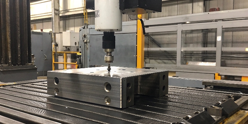
No die casting is 100% free of porosity. A good casting just keeps that porosity small, fine, and well-dispersed deep inside the part. However, if a designer specifies a deep machining cut in a high-risk area, you are asking for trouble. This is where early collaboration is key. During the DFM phase, we use mold flow simulation to predict where porosity is most likely to form. We then advise the customer to minimize or avoid machining in these critical zones. The other problem is the machining process itself. A dull tool doesn’t cut aluminum cleanly; it smears it. This can actually burnish the surface and hide a small pore, which might open up later. Aggressive cuts or machine chatter can also create a poor surface finish on an O-ring groove or gasket face, making it impossible to seal. I once solved a persistent leak issue for a U.S. client just by changing the toolpath for their main sealing face. Their original path caused vibration, but a new spiral path with a sharper tool created a much smoother, leak-free surface.
Why is poor flatness on sealing surfaces a major leak risk?
You have installed a high-quality gasket and torqued all the bolts to the exact specification. Despite this, the assembly still fails the pressure test. The problem may be invisible to the naked eye.
Gaskets need a uniformly flat surface to create a complete seal. If the casting’s sealing face is warped, bowed, or uneven, it creates microscopic gaps. Under pressure, air or fluid will easily find its way through these gaps, causing a leak.

Poor flatness can be caused by a few things. First, internal stresses built up during casting can be released during machining, causing the part to warp like a potato chip. This is especially true for large, thin-walled components like inverter housings. Second, the clamping method used during machining can distort the part. If you clamp a flexible part too hard or in the wrong spots, you machine it in a stressed state. When you release the clamps, it springs back to a non-flat shape. I was at a plant in Germany where they were struggling with flatness on a large housing. We checked their CNC fixture and found it was clamping the part right in the middle of a long, unsupported wall. The clamping pressure was causing the part to bow. We helped them redesign the fixture to support the part along its strong, outer perimeter. This small change ensured the part was held in a neutral, relaxed state during machining. The flatness problem disappeared, and their leak test pass rate went to 100%. Verifying flatness with a CMM is not optional for critical sealing surfaces; it’s a requirement.
How can a failing vacuum system lead to leaky parts?
You invested in a vacuum-assisted die casting process to produce high-integrity, airtight parts for an EV application. But you are still fighting porosity and leakage issues.
A vacuum system10 is supposed to remove air and gas from the mold before the metal is injected. If the system is not working perfectly—due to clogged vents, worn seals, or a weak pump—it leaves residual air behind. That trapped air causes gas porosity, the very defect you were trying to prevent.
A vacuum system is not a "set it and forget it" solution. It requires constant attention and maintenance to be effective. Air is pulled from the cavity through small vents and channels cut into the die. Over time, these vents can become clogged with aluminum flash or lubricant residue, reducing their efficiency. The seals between the two die halves or on the vacuum block itself can also wear out, allowing outside air to leak in and preventing the system from reaching the target vacuum level. I recall a difficult project involving a complex housing with very strict airtightness requirements. We noticed that porosity defects would appear randomly throughout the day. After checking everything else, we hooked up a data logger to the vacuum system. We saw that the vacuum level was dropping slightly just moments before the injection shot. A thorough inspection revealed a tiny, almost invisible crack in a vacuum hose. That small leak was enough to compromise the entire process. We now mandate a daily checklist for all our vacuum systems to check seals, vents, and pressures.
Could improper handling or testing be the real source of leaks?
You are confident in your casting and machining processes. The parts look perfect. Yet, a percentage of them are being rejected for leaks at the final inspection station.
Yes, sometimes the part is manufactured perfectly, but it gets damaged afterward. Or, the leak testing method itself is flawed. Dropping parts, stacking them incorrectly, or using the wrong test parameters can introduce damage or create "false failures" that waste time and money.

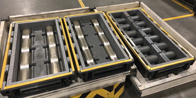
This is one of the most frustrating causes of leaks because the problem isn’t in the core manufacturing process. I always tell my team to treat every part with care, from the moment it leaves the die until it’s in the customer’s box. Aluminum is a relatively soft material. Dropping a part on a concrete floor or allowing parts to bang against each other in a metal bin can easily create a nick or dent on a critical sealing surface. We use custom-designed plastic dunnage and trays to protect every part during transport between operations. The testing method is another common issue. A customer might be testing a part at 2 bar when its real-world application only sees 0.5 bar of pressure. The higher pressure can create a "leak" that is not relevant. More importantly, the fixture used for the leak test can cause problems. I once visited a customer who was failing parts for leaks. We discovered that their test fixture, made of hard steel, was scratching the soft aluminum O-ring groove every time a part was loaded. The parts were fine, but their test was creating the defect. We helped them add a soft polymer insert to their fixture, and the problem was solved.
Conclusion
Ensuring a leak-free casting is not about one magic fix. It requires a holistic view of the entire process, from design simulation to final handling and testing.
-
Learn about common defects to improve your die casting processes and outcomes. ↩
-
Understanding gas porosity is crucial for improving casting quality and preventing leaks. ↩
-
Learn about cold shuts to enhance your die casting process and avoid leaks. ↩
-
Understanding machining damage is key to ensuring the integrity of your castings. ↩
-
Understanding flatness can help ensure proper sealing and prevent leaks in your components. ↩
-
Understanding mold venting can help you prevent gas porosity and improve casting quality. ↩
-
Learn the best practices for pressure testing to ensure your castings are leak-free. ↩
-
Discover how mold flow simulation can optimize your die casting process and reduce defects. ↩
-
Learn how to achieve leak-proof sealing surfaces for better performance. ↩
-
Learn about vacuum systems to enhance the quality of your die castings and prevent porosity. ↩


