

A 1.2mm nominal wall callout on an EV structural bracket or inverter housing lightweighting initiative sounds straightforward on a drawing. On the shop floor, it’s a different conversation — fill time drops into a window measured in milliseconds, gate velocity has to increase to avoid premature freezing, and the margin for error on shot control shrinks to almost nothing. This isn’t a "just reduce wall thickness" exercise; it changes which defects dominate, which alloys are viable, and how the tool has to be engineered.
This article covers what actually breaks at 1.2mm wall thickness, and the specific process levers that make it repeatable in production rather than a one-off trial success.
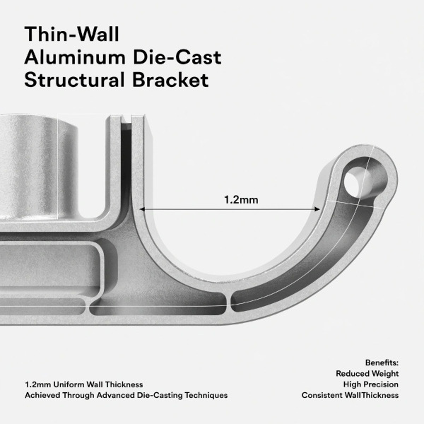
Why 1.2mm Is a Different Process, Not Just a Thinner Version of the Same One
At conventional wall thickness (2.5–4mm), the metal front has time to fill the cavity before the leading edge cools below the alloy’s solidification temperature. At 1.2mm, the surface-area-to-volume ratio roughly doubles compared to a 2.5mm wall, which means heat extraction into the die steel happens far faster relative to the volume of metal delivering that heat. If gate velocity and fill time aren’t recalculated for this ratio — not just scaled down — you get premature solidification (cold flow) before the cavity fills, especially at flow-length extremes.
| Parameter | Conventional Wall (2.5–3mm) | Thin Wall (1.2mm) |
|---|---|---|
| Typical gate velocity | 30–45 m/s | 45–60+ m/s |
| Fill time (medium-size part) | 25–40 ms | 8–15 ms |
| Surface-area-to-volume ratio impact | Baseline | ~2x baseline |
| Die steel thermal load per shot | Baseline | Elevated — faster local temp swings |
| Flow-length-to-wall-thickness ratio ceiling | 150:1–180:1 typical | Often exceeds 100:1 well before geometric flow length limit |
Challenge 1: Premature Solidification and Cold Flow
This is the dominant failure mode at 1.2mm. If the melt front loses fluidity before reaching the far end of the cavity, you get incomplete fill, cold shuts, or a visibly grainy/dull surface finish that also correlates with weak mechanical properties at that flow-length extreme.
What we do about it:
- Gate velocity is increased and gate cross-section is engineered specifically for the thin-wall zone rather than reused from a thicker-wall tool family — a gate sized for 3mm wall underfills a 1.2mm cavity almost every time
- Die temperature is run higher and more tightly controlled (typically 180–220°C at the cavity surface, vs. 160–200°C for conventional wall) to extend the fluid-flow window before the front freezes
- Moldflow simulation is run specifically to identify where flow-length-to-wall-thickness ratio approaches the alloy’s practical ceiling, and gate/vent placement is adjusted before the tool is cut, not after first trial
Challenge 2: Gas Entrapment Becomes More Damaging, Not Less
Counterintuitively, a thinner wall doesn’t mean less gas porosity risk — the higher gate velocity required to fill the cavity in time increases turbulence and air shear at the flow front, and at 1.2mm there’s less cross-sectional area available to "absorb" a trapped bubble without it showing up as a through-wall or near-surface defect.
What we do about it:
- VHPDC vacuum assistance is close to non-negotiable at this wall thickness; the porosity-reduction benefit of vacuum (discussed at length in our porosity-focused content) matters more here because there’s less wall thickness margin to bury a defect below the machined or sealing surface
- Overflow and vent placement is reworked specifically for the higher fill velocity, since standard vent sizing calculated for conventional wall thickness underperforms at the flow rates 1.2mm walls require
Challenge 3: Die Stress and Tool Life
Thin-wall tooling runs at higher injection pressure and intensification pressure to achieve the fill velocities required, and the thinner cavity steel sections (mirroring the thin part geometry) see more thermal cycling stress per shot.
| Tool Life Factor | Conventional Wall Tooling | Thin-Wall (1.2mm) Tooling |
|---|---|---|
| Cavity insert thermal fatigue rate | Baseline | Elevated — more frequent heat-checking inspection intervals |
| Core pin deflection risk (thin ribs/bosses) | Lower | Higher — smaller core cross-sections under same injection pressure |
| Recommended PM inspection interval | Standard OEM interval | Shortened interval, especially at high-stress gate and thin-rib zones |
We run tighter preventive maintenance intervals and more frequent dye-penetrant/visual inspection on thin-wall tooling specifically at the gate area and thin-rib cores, because heat-checking (thermal fatigue cracking) shows up faster here than on a conventional-wall tool running the same shot count.
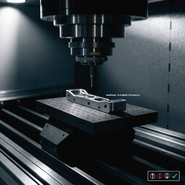
Challenge 4: Warpage and Dimensional Stability Post-Ejection
Thin sections cool and shrink faster than adjacent thicker bosses or ribs, and that differential cooling rate is the primary driver of warpage on thin-wall parts — not a tooling defect, a thermodynamic reality of the geometry.
What we do about it:
- Wall thickness transitions are reviewed during DFM specifically to avoid abrupt thick-to-thin jumps; where the part design requires a boss or rib intersecting a 1.2mm wall, we flag it for either a gradual transition radius or a design change, since abrupt transitions are the single most common warpage root cause we see
- Ejection sequence and pin placement are engineered around where the part is most prone to distortion during ejection while still hot, rather than a generic symmetric ejection pattern
- For dimensionally critical thin-wall parts, we hold post-ejection fixture cooling (constrained cooling on a check fixture) for a defined dwell time before the part goes to the next station — this is a real cycle-time cost, and we flag it during quoting rather than discovering it during PPAP
Alloy Selection for Thin-Wall Applications
Not every aluminum die-casting alloy is well-suited to 1.2mm walls. Fluidity at the required fill velocity matters more here than at conventional wall thickness.
| Alloy | Thin-Wall Fluidity | Typical Use Case at 1.2mm |
|---|---|---|
| AlSi9Mn | Good | General structural brackets, lower mechanical requirement |
| AlSi10MnMg | Good, better ductility | EV structural brackets requiring crash-relevant elongation |
| High-Fe recycled-content alloys | Poor | Generally avoided at this wall thickness — oxide/Fe-intermetallic content reduces fluidity margin that’s already tight |
We push back on secondary-grade alloy substitution for thin-wall programs specifically, even when it’s acceptable at conventional wall thickness, because the fluidity margin at 1.2mm doesn’t have room to absorb the additional oxide content typical of lower-grade recycled feedstock.
What This Means for DFM Conversations
When a customer brings us a 1.2mm wall spec, the DFM conversation isn’t "can you cast this" — it’s "where in the part does flow-length-to-wall-thickness ratio exceed what’s fillable, and where do wall-thickness transitions need softening before we cut steel." A thin-wall program that skips this step in DFM and goes straight to tool-cut is the most common path to a T1 trial that shows cold flow, warpage, or gas porosity that then requires a die rework cycle — which costs more time than doing the flow analysis upfront.
Bottom Line
1.2mm wall thickness is achievable in production aluminum die casting, but it requires gate velocity and fill-time engineering specific to that wall thickness (not scaled down from a thicker-wall baseline), VHPDC vacuum assistance as a near-default rather than an option, tighter die temperature control, shortened PM intervals on thin-wall tooling, and DFM review of every thick-to-thin transition before the tool is cut. Treated as a distinct process rather than a thinner version of conventional HPDC, 1.2mm walls are repeatable at production volume — treated as a drawing note applied after the fact, they’re where trial-and-error cycles eat the program schedule.


