

The bracket weighed 1.9 kg in ADC12, sat on a 630-ton machine, and had been running for three weeks before the customer sent back a photograph. A line ran along the top of a 4.2 mm rib, twelve millimetres from the gate, straight and grey, slightly darker than the metal around it. Six parts out of the box had the same line in the same place. Nobody had noticed it at the press because you can only see it when the light hits at a shallow angle.
The line was a cold shut, and the first thing we did was the thing everyone does first: raise the die temperature by 20 °C. The line moved four millimetres closer to the gate and stayed. That told us the problem was not heat, or not only heat, and the fix that actually worked was a change to the gate area and the fill pattern. This article is about the distinction, because the confusion between “too cold” and “two fronts that cannot weld” costs a lot of setup time.
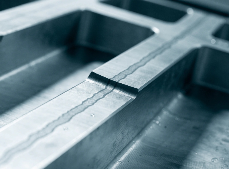
What a cold shut actually is
In high pressure die casting the cavity is filled by one or more streams of liquid metal. Each stream carries an oxide skin that forms within milliseconds of the metal touching air, and that skin is not a thin film of gas — it is solid aluminium oxide, roughly 4 to 8 nm thick at the temperatures we run, growing with time and turbulence. When two streams meet, the two skins meet first.
If the metal behind them is still liquid and hot enough, the skins break up and the fronts weld; the resulting line is invisible after machining and harmless. If the skins have had too long to form and the front has cooled too far, they do not break up. They fold together and stay folded. What you have then is a mechanical seam with an oxide interface inside it, and that interface has essentially zero tensile strength and, worse, it is a path.
A cold shut is therefore not a temperature defect in the sense people mean. You can run the die hot and still get one, if the two fronts had to travel too far or too slowly to reach each other in time. The oxide-film mechanism is documented outside the trade press too — a thesis on cold shut formation in castings from McGill’s repository works through the same physics with measurements, if you want the metallurgy rather than the shop-floor version.
Why the two fronts do not weld
Three variables decide it, and the one people watch least is the middle one.
Front temperature at meeting. The melt leaves the pot at 680 °C, arrives at the gate around 640 °C, and loses roughly 8 to 12 °C per 100 mm of travel through a 2.5 mm section. If the fronts meet below about 580 °C, welding becomes unreliable in ADC12; below 560 °C it is essentially over. This is why long thin sections cold shut at the far end and not near the gate — and it is the same physics that makes 1.2 mm thin-wall parts so unforgiving.
Time to contact. The oxide grows on a log scale with time, so the first 20 milliseconds matter more than the next 200. In a 38 ms fill, fronts that meet at 12 ms have a much better chance than fronts that meet at 35 ms. Fill time is set by gate area and shot speed, which is why adding gate area fixes cold shuts that die temperature cannot.
Front velocity and turbulence. A slow front is a cold front, but a violently fast front entrains gas and folds oxide into the part — you trade a cold shut for a lap or a gas pore. Our own experience on thin ribs is that 30 to 45 m/s gate velocity keeps the front moving without turning the cavity into a blender.
Reading the part: cold shut, cold lap, misrun
These three get used interchangeably in meeting rooms and they are not the same defect. They also get fixed differently, so naming them properly is worth the ten minutes. Our defect troubleshooting list covers the wider family; this section is only about the ones that come from two fronts meeting.
| Appearance | What happened | Where it shows up | How to confirm |
|---|---|---|---|
| Straight grey line, often with a slight step you can feel with a fingernail | Two fronts met and did not weld | Ends of long ribs, opposite gates, behind cores | Dye penetrant on a machined face; the line takes dye |
| Rounded, glossy fold, no sharp interface | Metal folded over itself without breaking the skin fully | Corners, changes of section, gate-adjacent areas | Cut and polish a section; the fold is visible under 20× |
| Edge or rib simply missing, rounded stub | Front froze before reaching the wall | Far end of the last-filled region | Visually obvious; check fill pattern on a short shot |
| Sharp thin fin outside the parting line | Die not locked, or flash from excessive pressure | Parting line, ejector pins | Measure the fin thickness; it is unrelated to fronts |
A short shot test is still the cheapest diagnostic in the plant. Run the shot at 60 % of the fill volume and look at where the metal stops. If the stop line is exactly where the cold shut appears in production, you have proof that it is a flow arrival problem, and you can stop adjusting temperatures.
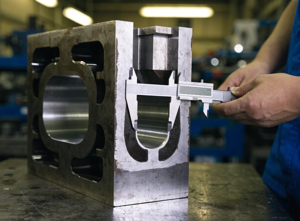
Five levers, ranked by what they cost
The order below is the order we actually try them, because the top two are usually free and the bottom two are not.
| Lever | Typical change | Effect on front temperature at meeting | Cost and risk |
|---|---|---|---|
| Die temperature, local | +30 to +50 °C in the cold zone, via a dedicated circuit | +15 to +25 °C | Low cost; can cause soldering if overdone |
| Gate area | +25 to 40 %, sometimes an extra gate | +20 to +35 °C through shorter fill time | Die modification, 1 to 2 days; scraps the insert if wrong |
| Gate position | Move the gate so the last-filled point is no longer a thin rib end | Depends; often the only real fix | New insert; 2 to 4 weeks |
| Vacuum | Cavity pressure below 100 mbar before fill | Indirect: allows faster fill without gas entrapment | Hardware; only pays when gas porosity is also a problem |
| Alloy and Fe content | Higher Fe improves hot strength but worsens ductility; Si raises fluidity | +5 to +10 °C of usable window | Cheap to change, expensive to qualify with the customer |
There is a sixth lever that people reach for because it is easy: raise the shot velocity. It does move the fronts faster. It also converts a cold shut problem into a gas porosity problem about half the time, and then you spend a month on vacuum because the X-ray now shows round voids instead of a line. If you are going to trade one defect for another, do it knowingly.
Why the X-ray passes parts that leak
This is the part of the conversation that changes customer meetings. A cold shut is a planar oxide interface. Its density is essentially the same as the aluminium around it, so a 2D X-ray sees almost nothing: there is no void for the beam to pass through. What the radiograph shows is a faint line at best, and only if the beam happens to be parallel to the plane. CT at 200 µm voxels has the same problem on a 10 µm interface.
So a part can pass 100 % X-ray inspection and leak on the machining line, because machining cuts through the seam and opens it. If the failure mode you care about is leakage, the inspection that finds cold shuts is dye penetrant on a machined surface, or a pressure decay test after machining — not radiography. This is the same thing the literature calls hidden damage: a 2024 study in Metallurgical and Materials Transactions B measured elongation at several positions in an Al-10 % Si HPDC part and found the scatter followed position, not shot-to-shot process data — damage done before solidification, invisible to the process record. We have written about vacuum-assisted porosity reduction elsewhere; that addresses round voids, and it does not address seams. The distinction matters because the two defects live in the same inspection budget and get confused in porosity control plans.
Machine-side quality control does not rescue you either, and that is now an active research topic rather than a shop-floor hunch. Conventional HPDC part screening is a tolerance check on individual logged parameters — if one falls outside its band, the part is scrapped. A 2025 paper in International Journal of Metalcasting argues that check is too crude and trains a model on machine data alone to flag bad parts right after extraction, before the part goes on to machining and powder coating. Their framing is the useful part for a buyer: the parameter bands can all be in range while the casting is not.
What we changed on the 2-gate bracket
The short shot confirmed the two fronts met at the rib top, 12 mm from the gate. Die temperature in that zone was 168 °C against 205 °C on the opposite side — a cooling circuit was partly blocked, which nobody had measured because the thermocouple was on the manifold, not the insert.
We did three things in one shutdown, which is not best practice but it was a Friday:
1. Cleared the blocked circuit and added a baffle, bringing the zone to 198 °C.
2. Opened the two gates from 3.2 mm² to 4.4 mm², cutting fill time from 41 ms to 34 ms.
3. Set a 200-piece trial with three process windows instead of one.
Result: cold shut rate went from 8.4 % to 1.1 % on the first window and to 0.3 % on the third. The remaining 0.3 % sits on parts where the rib is machined 0.6 mm deep, and those we now dye-penetrant after machining rather than pretending the press can solve it.
The honest cost of this was not the die work. It was the four days of production where we ran at 62 % of rate to keep the thermal window, and the customer conversation about why the PPAP sample had a defect nobody had specified a limit for.
Frequently Asked Questions
Can a cold shut be repaired by welding?
On a cosmetic surface, sometimes, with the customer’s written approval and a weld procedure. On a pressure-tight or structural part, no. Welding a seam that runs 12 mm into a 4 mm wall does not restore the section, and the heat-affected zone is a new fatigue initiation site. We have seen parts pass a post-weld leak test and fail in the field six months later.
Is a cold shut always visible?
No. A well-welded front leaves a flow mark that looks like a line but has full strength — you can only tell them apart by taking a section or by dye penetrant after machining. If the customer’s drawing calls for “no visible flow lines”, that is a cosmetic requirement and should be written as a surface class, not as a defect limit.
Does higher die temperature always help?
Up to a point. Above roughly 230 °C in the gate region on ADC12 you start soldering and die soldering-related erosion, and the front temperature gain per degree of die temperature is less than one to one. If 30 °C of die temperature does not move the defect, the problem is fill pattern and more heat will not fix it.
How do I specify this on a drawing so it does not come back?
Name the inspection method and the acceptance limit, not the defect name. “Dye penetrant per ASTM E1417 on machined surfaces, no linear indications over 2 mm” is checkable. “No cold shuts” is not, because two inspectors will disagree about whether a grey line is a flow mark or a seam.
Cold shut is usually a design conversation wearing a process costume. If the last-filled point is a thin rib end 12 mm from a gate, no amount of press tuning will make that a good place to end a fill. Change the place, and the defect goes with it.


