

Injecting molten aluminum at 700°C into a hardened steel die at 5 meters per second is a violently unstable thermodynamic event. If you expect a flawless, defect-free run just because your CAD model is geometrically sound, you are ignoring metallurgical reality.
On the high-pressure die casting (HPDC) floor, defects are inevitable. The difference between a struggling foundry and a reliable Tier 2 manufacturing partner lies entirely in diagnosing the root cause and adjusting the process parameters (PQ2, mold temperature, gating design) to drive those defects out of critical functional areas.
Based on decades of auditing and troubleshooting automotive die casting1 processes, here is a raw, engineer-to-engineer breakdown of the top 10 die casting defects, their actual root causes, and how we eliminate them before mass production begins.
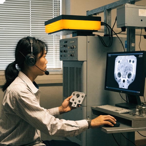
The Defect Identification Matrix
Before diving into the specifics, use this matrix to categorize the failure mode on your assembly line.
| Defect Category | Defect Name | Primary Root Cause Indicator |
|---|---|---|
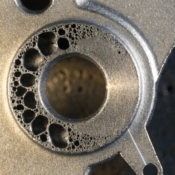
| Internal Voids | 1. Gas Porosity | Turbulent flow / Trapped air |
| Internal Voids | 2. Shrinkage Porosity | Severe thermal gradients / Lack of feeding |
| Surface / Flow | 3. Cold Shuts | Low metal or die temperature |
| Surface / Flow | 4. Blisters | Sub-surface trapped gas expanding under heat |
| Surface / Flow | 5. Galling (Soldering) | Overheating / Insufficient draft angles |
| Structural | 6. Hot Tears (Cracks) | Sticking during shrinkage / Uneven ejection |
| Structural | 7. Inclusions | Dirty melt / Oxide films in the furnace |
| Dimensional | 8. Thermal Warpage | Uneven cooling / Stressed CNC clamping |
| Dimensional | 9. Flash | Injection pressure exceeds clamping force |
| Functional | 10. Leakers (Weeping) | CNC machining exposing interconnected porosity |
Internal Integrity Defects
1. Gas Porosity
What it is: Smooth, spherical voids trapped inside the casting.
The Root Cause: Molten aluminum is violently sprayed into the cavity. If the plunger speed (fast shot) is triggered too early, or if the venting is inadequate, the atmospheric air inside the die is pulverized and trapped within the solidifying metal.
The Engineering Fix: We utilize Vacuum HPDC to evacuate the cavity milliseconds before injection. Additionally, we optimize the slow-shot profile to ensure a laminar flow that pushes air toward the vents rather than trapping it.
2. Shrinkage Porosity
What it is: Irregular, jagged voids typically found in the thickest sections of a casting.
The Root Cause: Aluminum shrinks by about 6% as it cools. Thin walls freeze instantly, cutting off the feeding path of liquid metal to the thicker bosses. As the thick boss cools, it tears itself apart internally because no fresh metal can reach it.
The Engineering Fix: You cannot cheat physics. We use Moldflow simulation to identify thermal hot spots and place conformal cooling channels directly inside the die block. If a design has severe thick-to-thin transitions, we force the use of coring to maintain uniform wall thickness according to strict NADCA design guidelines2.
3. Inclusions (Hard Spots)
What it is: Non-metallic particles (oxides, flux, or refractory material) embedded in the aluminum matrix.
The Root Cause: Poor melt quality. If the holding furnace is not properly fluxed and skimmed, or if rotary degassing is skipped, hydrogen and aluminum oxides are ladled directly into the shot sleeve. This destroys the tensile strength and will instantly break CNC cutting tools.
The Engineering Fix: Strict metallurgical discipline. We utilize spectrometer analysis on every melt to ensure compliance with ASTM material standards3, and employ rotary degassing and ceramic foam filters before the metal ever reaches the ladle.
Surface and Flow Defects
4. Cold Shuts (Flow Marks)
What it is: Distinct lines or seams on the surface where two flow fronts met but failed to fuse completely.
The Root Cause: The metal was too cold, or the fill time was too slow. By the time the two streams of molten aluminum collided, they had already formed a solid skin, preventing a homogenous fusion. This creates a severe weak point that will snap under dynamic fatigue.
The Engineering Fix: Increase the injection speed or raise the local die temperature. We rely on Moldflow to predict flow front temperatures, adding overflow wells to pull hot metal completely through the cold zones.
5. Blisters (Thermal Expansion)
What it is: Bubbles that form on the surface of the part, typically during T6 heat treatment or high-temperature powder coating.
The Root Cause: High-pressure trapped gas (gas porosity) hiding just beneath the dense outer skin of the casting. When the part is baked in an oven, the trapped air expands and pushes the softened aluminum skin outward.
The Engineering Fix: Vacuum HPDC is mandatory for any structural parts requiring T6 heat treatment (like shock towers or battery trays) to pull the gas out of the mold before it gets trapped.
6. Galling (Soldering)
What it is: Aluminum sticking or welding to the H13 tool steel, leaving drag marks on the part and damaging the mold.
The Root Cause: Either the die temperature locally exceeded the soldering threshold of the alloy, or the designer failed to provide adequate draft angles (tapers) on deep ribs and cores.
The Engineering Fix: Enforce a minimum draft angle of 1° to 1.5° on all internal geometries. On the foundry floor, we optimize the robotic spray of water-based release agents to cool the specific hot spots on the die face.
Dimensional and Functional Defects
7. Thermal Warpage
What it is: The casting bends or distorts after ejection, destroying flatness tolerances.
The Root Cause: Uneven cooling rates across a large part, or aggressive, unbalanced ejection forces pushing the part out of the die while it is still too hot.
The Engineering Fix: Implementing precise conformal cooling circuits. Furthermore, we do not force a warped raw casting into a rigid CNC fixture. We utilize low-distortion fixturing to ensure that machined faces remain perfectly flat after the clamps are released.
8. Hot Tears (Cracking)
What it is: Visible cracks in corners or intersections of the casting.
The Root Cause: As the aluminum solidifies and shrinks, it grips the steel cores tightly. If the part is constrained by sharp internal corners (lack of generous fillets) or if it is ejected unevenly, the shrinking metal will literally tear itself apart.
The Engineering Fix: Add generous radii to all internal corners to distribute stress, and balance the ejector pin layout to push the part out uniformly.
9. Flash
What it is: A thin web of excess metal escaping along the parting line of the die or around slider cores.
The Root Cause: The intensification pressure of the injection phase exceeded the clamping force (tonnage) of the machine, or the die faces are worn and no longer seal perfectly.
The Engineering Fix: Move the tool to a higher tonnage machine. If flash persists on a large machine, the tool steel itself may be deflecting under pressure and requires additional support pillars.
10. Leakers (Weeping Porosity)
This is the most critical failure mode for thermal management components.
What it is: Coolant or oil leaking through the solid aluminum wall of an EV motor controller housing4.
The Root Cause: The casting itself rarely leaks because the rapid chilling against the die wall forms a dense, watertight "skin." However, when secondary CNC machining cuts an O-ring groove right through that skin, it exposes the interconnected micro-porosity lurking in the core of the wall. Fluids will weep straight through this spongy internal network.
The Engineering Fix: We use simulation to shift thermal hot spots away from sealing surfaces. More importantly, we do not rely on visual checks. We utilize an automated quality control and inspection5 line with 100% air-decay leak testing to validate fluid-tight integrity before shipping.
Auditing the Reality of Die Casting
If your current supplier blames "bad luck" or "difficult geometry" for high scrap rates, they lack the metrology and thermodynamic control required for automotive manufacturing.
Quality cannot be sorted into a bin at the end of the line—it must be engineered into the tooling and the PQ2 diagram. Operating strictly under IATF 16949 standards6, EMP Tech utilizes predictive DFM and in-house Moldflow to identify and neutralize these 10 defects before we ever cut a block of H13 steel.
Experiencing high scrap rates on an existing project?
Upload your 3D CAD (STEP/IGES) via our contact form today. Our engineering team will provide a ruthless, objective diagnostic of your design’s castability and deliver a pragmatic manufacturing quote within 24 hours.
References & Footnotes
EMP Tech. Automotive Aluminum Die Casting Solutions & Capabilities. ↩
North American Die Casting Association (NADCA). Engineering & Design Standards. ↩
ASTM International. Standard Specifications for Aluminum-Alloy Die Castings. ↩
EMP Tech. EV Motor Controller Housing Engineering Specifications. ↩
EMP Tech. Automotive-Grade Quality Control & Inspection Laboratory. ↩
International Automotive Task Force. IATF 16949:2016 Quality Management System Requirements. ↩


