

At EMP Tech, we inherit tooling data packages that arrive with tight tolerances and aggressive timelines—and often with the same three or four failure modes already baked in. The problem is rarely the die casting machine. It’s the engineering assumptions that travel from the drawing board to the tool room without a proper DFM filter. As an IATF 16949-certified automotive die casting supplier1 running 13 vacuum high-pressure die casting (VHPDC) cells and over 150 CNC spindles, we see patterns. Here is why most projects hit the wall—and what actually prevents it.
1. The Porosity Panic
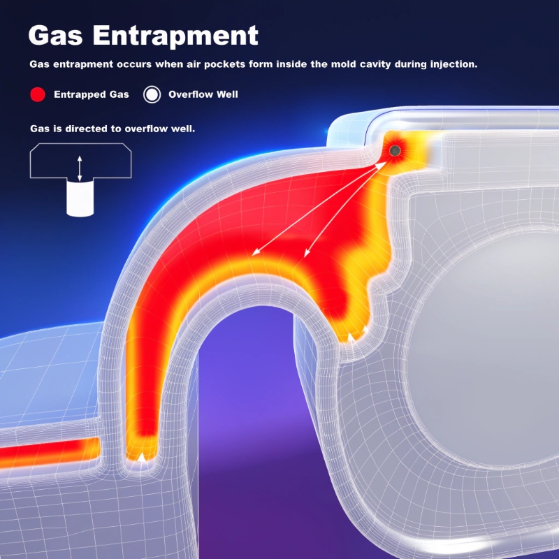
The drawing calls out “no porosity allowed,” but the part is a 3.2 kg transmission housing with wall transitions from 4 mm to 18 mm. Chasing absolute zero is thermodynamically illiterate. In VHPDC, dissolved gas and shrinkage discontinuities are managed, not eliminated. Our process routes the last solidification front into dedicated overflow wells by mapping the thermal field with Moldflow Insight before a single pocket is cut. According to NADCA’s practical guidance on gas porosity in structural die castings2, a well-designed gating and overflow system will concentrate microporosity in non-functional areas. The engineering conversation should be about acceptable discontinuity size, location, and frequency—not a blanket prohibition.
What kills a project is when porosity is discovered at PV testing because no one ran a CT slice on T1 samples. We baseline every first-off cavity with X-ray inspection and correlate the results with the Moldflow hot-spot prediction. Then we lock the process window.
2. Leak-Tight Specs Written in an Office
The O-ring groove on an EV motor housing has a 0.8 µm Ra callout and a flatness of 0.05 mm over a 400 mm sealing face. On a casting, that is not just a machining operation; it is a datum strategy problem. If the raw casting reference surfaces shift by 0.2 mm due to heat-check progression in the die, no CNC program can recover the groove location relative to the sealing flange.
We run single-setup 5-axis machining on our dedicated drivetrain housing cells3 specifically to eliminate re-fixture stack-up. But the more critical link is the upfront agreement on a datum hierarchy that survives casting variation. Too many projects lock the CMM alignment to a surface that the foundry process cannot hold stable. Then every PPAP run becomes a fire drill.

100% air-decay leak testing is our standard on housings that require IP67 or similar. We regularly see designs where the groove location tolerance band consumes the entire available gasket compression. The fix is never “machine more accurately.” It’s a DFM review that resizes the groove cross-section so the seal compression range absorbs the casting positional scatter.
3. The Machining Stack-up That Nobody Owned
A motor controller housing arrives with 27 tapped holes, five bearing bores, and a flatness spec on the connector face. The OEM engineer assumes the casting supplier controls the casting envelope, the machining supplier controls the bores, and the two will magically align. In a Tier-2 model, we own both. But if the design doesn’t leave enough stock for a rough-plus-finish pass on the critical bores, the cast skin can pull a cutting tool into taper.
We often see drawings where the cast surface profile tolerance on a sealing face is exactly the same as the machined surface tolerance. That effectively prohibits any machining—because any removal violates the as-cast tolerance unless the datum is renegotiated. The projects that succeed are those where we run a mold-flow-informed machining simulation before tooling steel is ordered, and the datum lock pins on the fixture are engineered jointly with the toolmaker.
4. Late-Stage Cleanliness Requirements
A transmission housing fails at PSW because the residual particle count inside the oil gallery exceeds the limit. The component was machined, washed, and bagged, but no one specified VDA 19 in the original statement of requirements. Retrofitting a validated cleaning process after tooling completion adds months.
Meeting VDA 19 technical cleanliness4 thresholds for functional components demands ultrasonic washing, controlled rinsing, and a cleanroom-adjacent packaging workflow. We introduced in-line particle monitoring on oil-wetted passages for EV housings because a 600-micron chip left from a drilling op can block a lubrication jet at 8,000 rpm. The key here is scoping cleanliness during the APQP Phase 1 risk assessment, not during the ISIR rejection meeting.
5. The PPAP Paperwork Time Bomb
A PPAP Level 3 submission includes dimensional results, material certifications, capability studies, and a signed PSW. The single biggest cause of PSW rejection we see is a mismatch between the CMM program and the customer’s ballooned drawing—usually because the drawing revision changed between the T2 sample and the submission run. With our in-house Zeiss CMM and PPAP workflow5, we flag these discrepancies before the measurement report is generated. An automotive Tier 1 cannot afford to resubmit a Level 3 package because the supplier misaligned the evaluation point numbering.
The second cause is insufficient run-at-rate data. If the PPAP lot is 300 pieces but the die was only run for 30 shots before, process stability is a gamble. We push for a minimum of 200 shots of thermal stabilization before a single dimensional record is taken, and the process capability data reflect that real-world scatter.
Projects fail when engineering intent is thrown over the wall without manufacturing data. They succeed when the supplier’s thermal, dimensional, and cleanliness capability data are treated as design inputs—not a post-mortem. That conversation starts at tooling kick-off.


