

In high-volume automotive die casting applications, gearbox housings rank among the most demanding structural components. These large, thin-walled parts with intricate oil channels, mounting bosses, and sealing surfaces must deliver precise dimensional stability under thermal cycling while maintaining leak-tightness. For Tier 2 suppliers squeezed between OEM requirements and machining partners, mold design decisions made early in the project directly determine PPAP success and production uptime.
At EMP Tech, we approach every large aluminum gearbox housing project through the lens of high-pressure die casting (HPDC) realities: metal flow dynamics, solidification behavior, and post-casting CNC interface requirements.
Core Challenges in Large Gearbox Housing Die Casting
Gearbox housings typically exceed 400 mm in length with wall thicknesses ranging from 3.5 mm to 8 mm in critical load zones. The combination of size and geometric complexity creates several predictable failure modes:
- Entrapped air and gas porosity in deep ribs and boss intersections
- Shrinkage porosity in thick-to-thin transition areas
- Cold shuts and misruns due to rapid heat extraction in thin sections
- Die soldering and heat checking on cores forming internal oil galleries
These issues become amplified when the part also serves adjacent functions, such as integrating with electric drive units where battery housing aluminum principles overlap in thermal management and structural rigidity requirements.
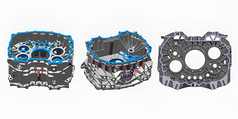
Mold Design Fundamentals for Complex HPDC Tooling
Effective mold design starts with parting line strategy and slide/core layout. For gearbox housings, we prioritize:
- Main parting line placement to minimize flash on sealing surfaces
- Multiple side cores for undercut oil channels and sensor bosses
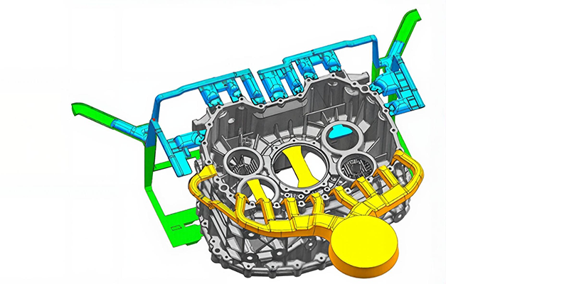
- Overflow and vent placement optimized through iterative simulation
The gating system deserves particular attention. We typically employ a fan gate or multiple tangential gates feeding into the thickest sections first, allowing directional solidification toward the overflows. Plunger velocity profile is tuned to achieve 30-45 m/s at the gates while keeping intensification pressure above 800 bar to compress residual gas.
Critical design parameters we control:
| Parameter | Typical Value | Rationale |
|---|---|---|
| Gate velocity | 35-42 m/s | Balance filling time vs. die erosion |
| Overflow volume | 15-25% of casting | Effective air/gas evacuation |
| Cooling line distance to surface | 12-18 mm | Uniform heat extraction |
| Draft angles (internal) | 0.75-1.5° | Ejection without distortion |
| O-ring groove Ra | ≤ 0.8 μm (post-CNC) | Sealing performance |
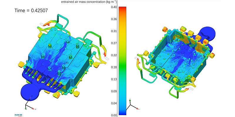
Mold Flow Simulation as Engineering Cornerstone
Mold flow simulation is not a checkbox — it is the primary tool for de-risking large structural castings. Using software like MAGMA or Flow-3D, we model the entire process including:
- Filling phase with accurate piston motion and turbulence prediction
- Solidification with temperature-dependent material properties for AlSi10MnMg
- Residual stresses and distortion prediction for CNC fixture design
- Vacuum system integration effectiveness
One insight from our shop floor: the standard simulation often underestimates the impact of die preheat temperature gradients on real-world flow. We routinely validate simulation outputs against short-shot studies on the actual machine, adjusting plunger tip lubrication and die spray patterns accordingly. This closed-loop approach has repeatedly eliminated cold shut defects in complex gearbox housings that initial simulations suggested were "acceptable."
For projects sharing architecture with battery housing aluminum components, cross-learning on large flat surfaces and heat dissipation channels accelerates optimization.
Material Selection and Metallurgical Control
AlSi10MnMg (similar to A365) remains the go-to alloy for structural gearbox housings due to its combination of castability, strength after heat treatment, and corrosion resistance. Key process controls include:
- Melt temperature: 680-720°C at the shot sleeve
- Iron content strictly below 0.15% to minimize sludge formation
- Sr modification level verified by thermal analysis
- Degassing to hydrogen content < 0.15 ml/100g
We never promise "zero porosity" — instead, we engineer porosity location and morphology so that critical machined surfaces remain sound. Porosity in non-functional ribs or bosses is acceptable and often unavoidable; the art lies in moving it there predictably.
Post-Casting CNC Interface and Tolerances
The mold must be designed with CNC machining in mind. We target as-cast tolerances of ISO 2768-m for most features, knowing that critical sealing planes and bearing bores will require 5-axis CNC finishing. Particular attention goes to:
- O-ring groove locations and depths (critical for leak testing)
- Core pin placement repeatability (±0.05 mm)
- Ejector pin marks positioned away from functional surfaces
Our in-house 5-axis machining experience informs mold design decisions that reduce fixture complexity and cycle time downstream.
Quality Systems and PPAP Level 3 Delivery
For OEM die casting supplier qualification, PPAP Level 3 documentation must reflect actual process capability, not theoretical ideals. We provide:
- Full dimensional layout on Zeiss CMM equipment1
- X-ray and CT scan porosity mapping
- Process FMEA with real shop floor data
- Material certification and heat treatment records
This level of transparency helps Tier 2 suppliers navigate IATF 16949 audits with confidence, especially when managing multiple sub-suppliers.
Practical Lessons from Production Runs
After running hundreds of large structural tools, one recurring insight stands out: die thermal cycling management determines tool life more than any other factor. We implement segmented cooling circuits with independent flow control for areas experiencing different thermal loads. This not only extends die life beyond 80,000 shots on complex tools but also stabilizes part-to-part dimensional variation.
Another observation: vacuum levels that look excellent on the gauge (≤ 50 mbar) can still yield porosity if vent design is inadequate. The vents must remain functional after multiple cycles — this requires careful land design and periodic cleaning protocols.
Partnering for Complex Die Casting Projects
Whether your project involves next-generation transmission housings or integrated e-drive components, successful mold design requires deep collaboration between simulation, tooling, casting, and machining teams.
For automotive manufacturers and Tier 2 suppliers seeking reliable OEM die casting supplier capability for large aluminum components, the difference lies in the details of mold engineering and process control.
References & Footnotes
This approach to die casting automotive applications consistently delivers parts that meet stringent OEM specifications while maintaining economical cycle times.
EMP Tech. Automotive-Grade Quality Control & Inspection. Verified through coordinate measuring systems and industry-standard protocols. ↩


