

Key Considerations for Post-Processing of Die-Cast Parts
Post-processing of high-pressure die casting (HPDC) components is where many projects succeed or fail under OEM scrutiny. For Tier 2 suppliers delivering structural aluminum parts—particularly motor housing die casting or large EV structural castings—the casting itself is only the starting point. Dimensional capability, sealing integrity, and surface condition after machining determine whether the part clears PPAP Level 3 and survives the customer’s leak and durability tests.
At EMP Tech we treat post-processing as an integrated extension of the casting process rather than a separate operation. Decisions made in gating, overflow design, and solidification control directly dictate machining strategy, fixture design, and final yield.
Primary Post-Processing Operations for Automotive HPDC Parts
Typical sequence for complex aluminum die castings (motor housings, gearbox cases, battery trays):
- Shot blasting / vibratory finishing to remove flash and improve surface for subsequent operations
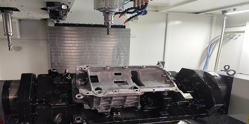
- CNC machining (3- to 5-axis) of sealing planes, bearing bores, and mounting features
- Deburring and edge radius control
- Impregnation or local porosity sealing where required
- Heat treatment (T5 or T6) when mechanical properties demand it
- Surface treatment (e-coat, powder, or conversion coating)
- Final inspection and packaging
Each step introduces variation that must be controlled against the original casting geometry and residual stresses.
Dimensional Stability After Machining
As-cast tolerances under ISO 2768-m are rarely sufficient for sealing surfaces or bearing bores. Critical features routinely move to ±0.05 mm or tighter after CNC. The challenge is predicting and compensating for residual stress relief during material removal.
Key shop-floor observations:
- Thin-wall sections (3–5 mm) adjacent to thick bosses release stress differently. Fixture design must support the part in the same orientation as final assembly to avoid spring-back.
- Core-pin locations that form oil galleries or coolant passages often leave localized residual stress. We map these zones with residual-stress measurement before final machining programs are locked.
- For motor housing die casting, the stator bore and bearing seats are the most sensitive. We leave 0.8–1.2 mm machining stock and use sequential roughing–finishing cycles with intermediate stress-relief checks.
| Feature Type | Typical As-Cast Tolerance | Post-CNC Target | Stock Allowance |
|---|---|---|---|
| Sealing plane | ISO 2768-m | ±0.05 mm | 0.6–1.0 mm |
| Bearing bore | ±0.15 mm | H7 / IT7 | 0.8–1.2 mm |
| O-ring groove depth | ±0.10 mm | ±0.03 mm | 0.4–0.6 mm |
| Threaded hole position | ±0.20 mm | ±0.05 mm | 0.5 mm |
Surface Integrity and Sealing Performance
O-ring grooves and gasket faces are common failure points. Cast surface roughness after shot blast is typically Ra 6–12 μm. CNC finishing must bring critical grooves to Ra ≤ 0.8 μm without introducing chatter or tool marks that create leak paths.
Practical controls we enforce:
- Dedicated finishing tools with controlled edge radius
- Coolant filtration to below 10 μm to prevent particle embedding
- 100 % visual and tactile inspection of groove bottoms before impregnation decisions
Porosity intersecting the machined surface remains the most frequent root cause of leaks. We do not claim zero porosity. Instead we locate porosity away from sealing zones through mold-flow-driven overflow placement and then apply vacuum impregnation only where necessary. Full-part impregnation is avoided on large EV structures because of cost and potential residual resin issues in subsequent coating.
Heat Treatment Considerations
Many structural automotive die castings and aluminum die casting for EV applications require T5 or T6 treatment to reach the specified yield strength. The timing of heat treatment relative to machining is critical:
- T5 (artificial aging only) is preferred when dimensional stability is paramount; distortion is lower.
- T6 (solution + aging) delivers higher properties but introduces greater risk of distortion on large open structures such as motor housings.
We run process capability studies on both sequences and lock the order based on the customer’s final GD&T requirements. Quench rate after solution treatment is controlled to minimize residual stress while still achieving the required microstructure.
Leak Testing and Non-Destructive Evaluation
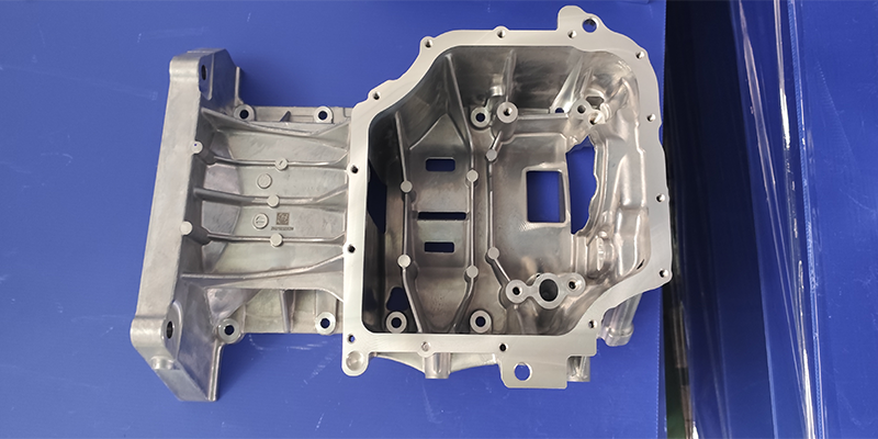
Helium or air-under-water leak testing is standard for motor housings and gearbox cases. Test parameters must reflect the actual sealing system (O-ring compression, gasket material, assembly torque). We correlate leak-test results with CT porosity maps so that reject criteria are based on functional risk rather than arbitrary size thresholds.
X-ray or CT is applied on a sampling basis for new tools and then reduced once process capability is demonstrated. Full CT on every part is rarely economical for high-volume HPDC; targeted scanning of high-risk zones is more effective.
Coating and Corrosion Protection
E-coat or powder coating is common for underbody and under-hood components. Surface preparation after machining is decisive: residual cutting fluid, impregnation resin, or blast media will create adhesion failures. We specify alkaline cleaning + conversion coating sequences validated to the OEM’s salt-spray and cyclic-corrosion requirements.
For EV motor housings, electromagnetic compatibility and thermal interface surfaces often remain uncoated. These zones require special masking and post-coating cleaning protocols to avoid contamination.
Documentation and PPAP Readiness
Tier 2 suppliers face intense pressure to deliver complete PPAP Level 3 packages that include:
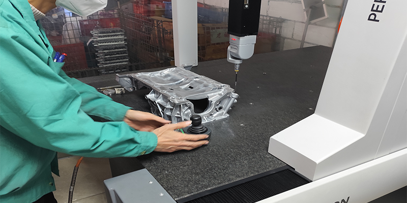
- Dimensional reports from Zeiss CMM equipment1 correlated to the casting and machining datums
- Material certificates and heat-treatment records
- Process capability (Cpk) for critical characteristics
- Leak-test and impregnation process validations
We generate these data sets from the same measurement systems used in production so that the PPAP reflects actual process performance rather than idealized first-article results. This approach reduces the risk of late-stage audit findings when the part moves into series production.
Practical Trade-offs Observed on the Floor
One recurring insight: over-machining “to be safe” often creates more problems than it solves. Excessive stock removal increases cycle time, tool cost, and residual-stress risk. We prefer to tighten casting process control (gate velocity, intensification pressure, die thermal balance) so that machining stock can be reduced while still guaranteeing clean-up of all functional surfaces.
Another observation: impregnation is a corrective action, not a design feature. When porosity consistently appears on sealing surfaces, the correct response is mold modification—relocating overflows or adjusting venting—rather than permanent reliance on resin sealing.
For projects requiring both high structural integrity and tight sealing performance, collaboration between the aluminum die casting manufacturer2 and the machining partner must begin at the mold-design stage. Late changes to machining stock or fixture strategy after tool steel is cut are expensive and time-consuming.
Whether the component is a conventional automotive die casting or a next-generation EV motor housing, post-processing success is determined by how thoroughly the casting process and secondary operations are engineered as a single system.
References & Footnotes
EMP Tech. Automotive-Grade Quality Control & Inspection. CMM programs and process capability data used for PPAP Level 3 submissions. ↩
EMP Tech. Automotive Die Casting Solutions. Core capabilities for structural aluminum components including motor housings and EV applications. ↩


