

Aluminum structural components for EVs: the drawing never says where
An RFQ arrived last month with one line I keep seeing: “Aluminum structural components for electric vehicles, 8.2 kg, AlSi10MnMg, Rp0.2 min 120 MPa, A min 10 %.” Seven pages of geometry, one grade, one property pair, no location. So the part is structural, and the client wants ductility — but a structural casting does not have one elongation. It has a map.
I asked which zone carries the crash load. The buyer sent the drawing tree, which told me the answer was in the front longitudinal, between the two suspension pickup points, and that nothing else mattered much. That single sentence changed the quote by 14 %. Not because of material — the alloy was the same — but because it moved the gate, the overflow, the heat treatment spec and the sampling plan.
Below is how I decide, before tooling, whether a structural part can be made by high-pressure die casting at all, and what has to be written down for it to be checkable afterwards.
What “structural” actually buys you
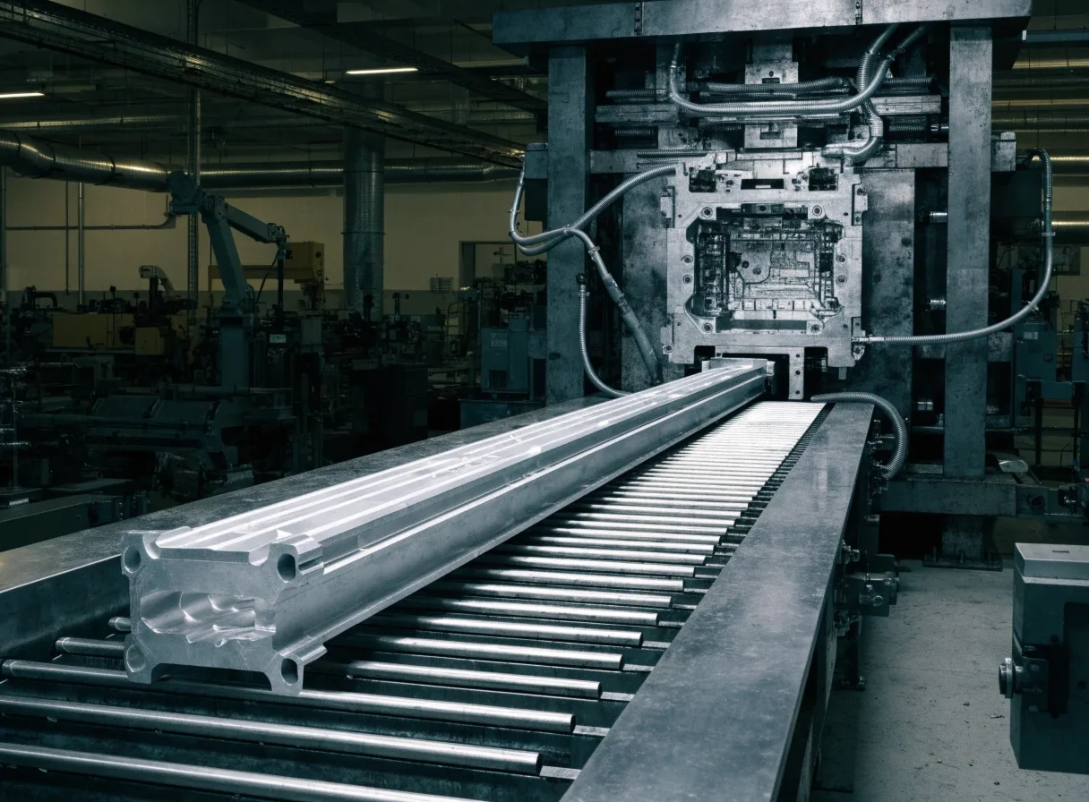
Structural means the part is in the load path: it carries suspension forces, crash energy, or battery mass. Three consequences follow, and each one lands in a different part of the drawing.
- Load path. The section that must not tear is a specific area, not the whole casting. Property requirements belong to that area, dimensioned and hatched.
- Energy absorption. Crash behaviour depends on elongation and on how the part fails. A casting that yields at 200 MPa but tears at 3 % elongation behaves worse than one at 180 MPa and 9 %.
- Fatigue and sealing. Motor housings and battery trays add a fourth requirement — no through-wall porosity — which is a different acceptance test from strength.
Once I write these three as separate line items, the argument about “is HPDC good enough” usually disappears. HPDC is good enough for a defined zone, and it is not good enough for an undefined one.
The fill path is a property gradient, not a detail
The most useful number I have found on this came out of a study on a vacuum HPDC AlSi10MnMg rear longitudinal beam. The authors measured the same part along the filling direction and found the eutectic silicon fraction rising from 45.86 % near the gate to 72.66 % at 702 mm away. Elongation followed the silicon down. Pores at the far end were both more numerous and larger than near the gate, and the micropores grew further during heat treatment. Small polygonal Al-Mg and Fe-Mn phases, 2.5 to 7 μm, concentrated in the far-gate region. (China Foundry, 2025)
Two practical readings, and they point in opposite directions:
First, a single elongation figure on a long structural casting is a fiction unless it is attached to a location. “A ≥ 10 %” measured on a coupon cut near the gate proves nothing about the end that sees the load. I ask for the zone, then I put the tensile specimen there.
Second, the same study gives the levers: higher injection velocity and longer holding time both improved toughness, provided composition and vacuum level stayed controlled. That matches what the machine data says on our own cells — when elongation is short on one end, the fix is usually fill time and intensification, not a stronger alloy. Related: how vacuum level and porosity interact on the same parts.
| What changes along the fill path | Direction | What I do about it |
|---|---|---|
| Eutectic silicon fraction | 45.86 % near gate → 72.66 % at 702 mm | Put the gate so the load zone sits early in the fill, not last |
| Elongation | Falls with distance | Specify A per zone; sample the far end, not the easy end |
| Porosity | More and larger far from gate | Overflow and vent at the end, then radiograph that region |
| Intermetallics after heat treatment | 2.5–7 μm phases concentrate far-gate | Keep heat treatment out of the ductility-critical zone, or accept lower A |
Distortion grows faster than the part does
On a 1.4 kg bracket, distortion is a note in the drawing. On an 8 kg structural casting it is the reason the project fails. The mechanism is not mysterious: solidification shrinkage, thermal gradients, and residual stress released during machining all move the same way, and their sum scales with length.
A 2025 study on gigacasting-scale parts attacked it the way I would: simulate with in-mould temperature and pressure data rather than with a nominal cooling curve, model ejection pressure, then cool to room temperature and compare against a laser scan of the real casting. (Int. J. Metalcasting, 2025)
The lesson for a supplier who is not running gigacasting is simpler than the method: quote distortion as a band, and prove the band on five parts before you cut the second tool. I have watched two projects die because the tolerance was quoted from a table and the first article arrived 0.6 mm out on a datum that nobody had defined. Datum scheme first, then the number.
What gigacasting changes, and what it does not
The current state of the art is well summarised: 6000 t machines, up to 70 parts consolidated into one, rear underbody stiffness up about 23 %, factory footprint down about 40 %, with AlSi10MnMg targets around 300 MPa tensile strength, above 10 % elongation, vacuum better than 95 % and porosity under 0.5 %. (Frontiers in Mechanical Engineering, 2026 review)
What that changes: part count, tooling count, assembly, and the size of the risk. One casting instead of seventy means one process window to control and one failure mode to catch — but it also means a single out-of-window shift scraps a week of production instead of an hour.
What it does not change: the tolerance system. A 3 m casting is still bought against a table of dimensional grades, not against a single ± number. ISO 8062-3 works by basic size and casting tolerance grade, and the grade you can hold depends on the feature — a machined bore, a die-drawn wall, and a parting-line surface are three different conversations. The same logic governs draft and machining allowance as written in the NADCA product specification standards.
Where I have seen optimism go wrong most often is thickness. Structural castings want 2.5 to 3.5 mm nominal wall with ribs, not 1.5 mm everywhere. Walls thinner than about 2 mm stop being a die casting problem and become a wrought or a stamped problem. On the other end, sections above roughly 6 mm centreline hold porosity no vacuum will fully remove; if the FE model demands a 10 mm boss, that boss needs its own discussion.
What I put in the RFQ for a structural casting
Five lines, in this order. They cost the buyer twenty minutes and save both sides a tool.
- Load zone, defined. Hatch the area on the drawing and state the property there. If the whole part must pass, say so and expect a different process.
- Property map accepted. A band per zone beats one global number. I will happily sign “A ≥ 8 % in the crash zone, ≥ 4 % elsewhere” because I can control it.
- Distortion band plus datum scheme. Which surfaces are datums, who machines first, and what the allowance is. Without this, the first article is a negotiation.
- Porosity acceptance by area. Pressure-tight zones get 100 % leak test after machining; cosmetic zones get a visual standard; structural zones get radiography at a stated sampling rate and a stated acceptance level.
- Heat treatment intent. T5 or T6 changes both ductility and distortion. If the client wants T6 for strength, the distortion number must be re-quoted — they are the same decision.
| Check | Method | Cost of skipping it |
|---|---|---|
| Properties in the load zone | Tensile specimens cut from the far end of the fill | Certificates that pass, parts that fail in validation |
| Distortion before tooling | Simulation with in-mould data, then 5 first articles on a laser scan | Second tool or a fixture that fights the part forever |
| Porosity in sealing areas | Radiography plus 100 % leak test after machining | Leaks found at the customer, at 30× the cost |
| Tolerance per feature | Dimensional grade table, not one global ± | Quotes that are 15 % off in both directions |
Where HPDC stops working
I would rather name the boundary than defend the process. HPDC stops working when the part needs uniform elongation across 2 m of fill, when it needs wrought-grade ductility above 12 % everywhere, when the wall goes below 2 mm over a large area, when a single thick section drives the whole solidification, or when the geometry has to change after the tool exists in a way that alters the load path.
It works well when the load zone is defined, the gate can put good metal there first, the tolerance is quoted per feature, and someone is willing to radiograph the end nobody likes to look at. That is not a compromise on quality; it is the actual specification. Related reading on how die thermal balance drives scrap and on buying tight tolerances without buying trouble.
Frequently Asked Questions
Can high-pressure die casting hold 10 % elongation over a whole large structural part?
Rarely, and not uniformly. The same AlSi10MnMg part shows falling elongation as fill distance grows, because eutectic silicon and porosity both increase away from the gate. A zone-specific requirement is realistic; a global one over 700 mm of fill is a different process or a different alloy.
Is vacuum HPDC the same thing as structural casting?
No. Vacuum reduces gas porosity; structural casting adds a property requirement in a defined zone, usually with heat treatment, tighter process control and per-area acceptance testing. Vacuum is one input, not the definition.
Do structural castings need T6?
Only if the design needs the strength. T6 raises yield and tensile strength but costs ductility and worsens distortion, and on a large part the distortion is the expensive half. Many structural parts run T5 or as-cast with a zone-specific spec.
How can distortion be proven before the tool is cut?
Simulate with in-mould temperature and pressure data, model ejection, then commit to a measured band on the first five parts. The simulation is not the proof; the five laser-scanned parts are.


