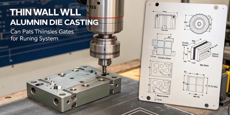
A thin-wall die casting project can fail fast. Parts warp, leak, crack, or miss cycle time. I will show you the key points that protect launch timing.
Thin wall aluminum die casting for automotive works best when I control wall thickness, flow length, vacuum, thermal balance, alloy choice, and machining strategy together. Most failures come from treating these items separately. I use one DFM and process window from the start.
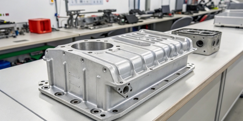
I have worked on motor controller housings, OBC housings, and structural die castings for new energy vehicle projects. I learned one simple lesson. Thin wall parts do not forgive weak early decisions. If you are a supplier quality engineer or a purchasing leader, keep reading. I will break this topic into the real checks that decide whether a supplier can run stable mass production.
What is considered thin wall aluminum die casting in automotive?
Many teams use the phrase thin wall too loosely. That creates wrong quoting, weak DFM, and process promises that collapse during trials. I prefer a practical definition.
In automotive aluminum HPDC, I usually call 1.5–2.5 mm a thin-wall range. Below 1.5 mm, the project becomes much more sensitive to flow, venting, die temperature, and gating design. The full part geometry matters more than one nominal wall value.
How I judge thin wall parts in real projects
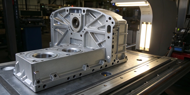
I do not judge a part by one number on the drawing. I look at the full filling path, local hot spots, rib layout, bosses, sealing faces, and where the machining stock sits. A 2.0 mm housing can be easier than a 2.8 mm part if the flow path is short and the section changes are smooth. I have seen teams call a part “safe” because the average wall was 2.5 mm. Then they hid 1.4 mm corners and deep ribs in the model. That always causes trouble in trial runs. I check five things first: minimum wall, flow length to thickness ratio, gate position, vent path, and expected distortion after trim and machining. I also ask if the part needs leak tightness, welding, or heat treatment later. That changes the real process window. For me, a thin-wall automotive die casting is not just a thin section. It is a part whose success depends on precise control of fill speed, vacuum, die thermal balance, and structural geometry together.
| Item I check first | Typical concern in thin wall parts |
|---|---|
| Minimum wall thickness | Incomplete fill, cold shut |
| Long flow path | Flow freeze before full cavity fill |
| Deep ribs or bosses | Air trap, shrinkage, distortion |
| Tight sealing face | Leak risk after machining |
| Thin-to-thick transition | Hot spot, sink, porosity |
| Flatness requirement | Warpage after ejection or aging |
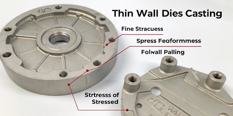
Why do thin wall die castings fail more easily?
A thin wall casting gives me less margin. The melt cools fast, the air has less time to escape, and even a small thermal imbalance can change the result. That is why many “good” tools still run badly.
Thin wall die castings fail more easily because molten aluminum loses temperature quickly in narrow sections. This raises the risk of cold shuts, misruns, gas entrapment, distortion, and local porosity. Stable results need matched control of die design, vacuum, metal temperature, and shot profile.
The failure modes I see most often in launch
I usually see five repeat problems. The first is incomplete fill, often at the end of fill or around weak vents. The second is cold shut at section joins where two metal fronts meet too cold. The third is gas porosity from poor venting or unstable vacuum timing. The fourth is distortion after ejection because one side of the die ran hotter and the stress locked into the part. The fifth is machining exposure, where a sealing face looks fine before CNC and then opens pores after stock removal. I once supported a controller housing that passed visual checks but failed leak testing after finish machining. The root cause was not machining. The root cause was poor overflow placement that trapped air near the sealing band. We changed the overflow and cooling layout, and the leak rate dropped sharply. This is why I always tell customers that thin wall failure is usually system failure, not one single defect. If the gating, vacuum, die cooling, and geometry do not support each other, no operator can “fix it” on the machine.
| Failure mode | Typical root cause | What I check |
|---|---|---|
| Misrun | Melt cools too fast | Fill time, gate speed, die temp |
| Cold shut | Two fronts meet too cold | Flow pattern, gate layout |
| Gas porosity | Poor venting or weak vacuum | Vacuum curve, vent area |
| Warpage | Uneven thermal balance | Die cooling map, eject timing |
| Leak after machining | Hidden pores in sealing area | CT, section cut, stock plan |
Which alloys are best for thin wall automotive die casting?
Picking the wrong alloy can block the whole project. One alloy may fill well but crack in use. Another may machine well but fight corrosion or welding. I always tie alloy choice to function.
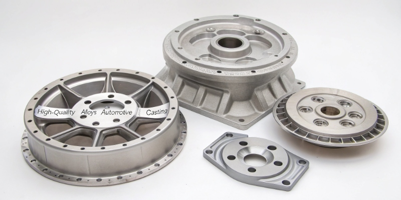
For thin wall automotive HPDC, I often see AlSi10MnMg, AlSi10Mg, or AlSi9Cu3 depending on structural need, corrosion risk, heat treatment plan, and cost target. I do not choose alloy by strength alone. I choose by the whole application.
How I match alloy to part function
I start from the service conditions. If the part is a housing with high corrosion concern and moderate structural duty, I lean toward AlSi10MnMg or AlSi10Mg depending on the downstream needs. If the part needs very high productivity and cost pressure is strong, many suppliers push AlSi9Cu3. That can work for many non-welded housings, but I stay careful when leak tightness, heat treatment, or corrosion life matter. For structural parts, I need stronger ductility control and tighter porosity management. Then alloy choice and vacuum discipline become linked. I also check whether the customer plans any local welding, impregnation, chromate-free coating, or severe environmental cycling. I learned this the hard way on one project where the alloy filled beautifully in trial runs, but the field duty cycle and corrosion path made it the wrong long-term choice. Since then, I never approve alloy before I see the full use case, surface treatment, and validation matrix.
| Alloy | Common use | Main advantage | Main caution |
|---|---|---|---|
| AlSi10Mg | Housings, some structural parts | Good balance, corrosion support | Needs tight porosity control |
| AlSi10MnMg | Structural automotive castings | Better ductility path | Strong process discipline needed |
| AlSi9Cu3 | High volume housings | Cost and productivity | Corrosion and weld limits |
| A380 / ADC12 type | General HPDC parts | Easy sourcing | Not ideal for high integrity parts |
What design rules help thin wall die castings succeed?
A weak design makes even a strong supplier struggle. A good design gives the process room to breathe. I always push DFM before tool release, not after T1 failure.
Thin wall die castings succeed when wall thickness stays uniform, ribs are used carefully, transitions are smooth, sealing faces are protected, and gates support short balanced flow paths. Good design lowers porosity, warpage, and machining risk.
The DFM rules I use before tool kick-off
I like to keep nominal walls in a narrow band. I try to avoid sudden jumps because they create hot spots and pull. I use ribs to build stiffness, but I keep them proportionate to the wall and avoid turning the rib root into a shrinkage trap. I ask for smooth radii at all section changes. Sharp corners kill flow and build local stress. I move sealing bands away from last-fill areas whenever I can. I also protect machining datums. If I place a critical datum in a porous zone, I create a problem before casting starts. On larger housings, I look at flange flatness early. Many teams check flatness too late, after they already fixed the gate and cooling layout. I also review ejector position because thin walls can deform during ejection. These are basic rules, but they are often ignored when the program is rushing. In my experience, a two-hour DFM review before tool design can save two months of tool rework after T1.
| Design feature | My practical rule |
|---|---|
| Nominal wall | Keep as uniform as possible |
| Ribs | Add stiffness, avoid heavy rib roots |
| Corners | Use smooth radii |
| Sealing face | Keep away from last-fill zones |
| Datum areas | Put in stable, low-porosity zones |
| Flat flanges | Review cooling and support early |
What process controls matter most in production?
A capable tool can still fail in mass production. Many plants lose stability not in design, but in daily process drift. I focus on a few controls that truly matter.
The most important process controls are vacuum stability, die temperature balance, melt quality, shot profile consistency, spray control, and trimming discipline. In thin wall HPDC, small drift in these inputs can quickly create leak, flatness, or strength issues.
The production controls I ask suppliers to prove
When I audit a supplier, I do not stop at the machine setting sheet. I want trend data. I ask for vacuum curves, not only a target value. I ask for die face thermal images by cavity area, not just one average die temperature. I review melt handling, transfer time, and cleanliness. I look at shot sleeve lubrication discipline because inconsistency there changes filling behavior. I also want to see how the team controls spray amount and spray position. Too much spray cools the die unevenly. Too little spray creates sticking and local heat build-up. Then I check trim and handling. Thin wall parts can bend after casting if the trim sequence is rough or the part support is weak. On one project, the root cause of flatness failure was not casting at all. It was poor post-cast handling when hot parts were stacked without support. After we changed the rack and cooling route, the flatness issue nearly disappeared. That taught me again that process control must include what happens after ejection, not only inside the die casting cell.
| Process control | Why I care |
|---|---|
| Vacuum curve | Direct link to gas porosity |
| Die thermal balance | Controls fill, distortion, sticking |
| Melt cleanliness | Affects defects and consistency |
| Shot profile | Controls fill speed and front stability |
| Spray control | Changes local die temperature |
| Post-cast handling | Impacts flatness and damage |
Conclusion
Thin wall automotive die casting succeeds when I align design, alloy, vacuum, thermal balance, and handling early. If one link is weak, launch risk rises fast.


