Shipping a part with a hidden defect can destroy your project and reputation. Without the right inspection tools, critical flaws in dimensions, material, or porosity can go undetected until they fail in the field.
A robust inspection process for die castings relies on a toolkit of specialized equipment. This includes a CMM for dimensional accuracy, an X-ray system for internal porosity, a spectrometer for alloy verification, and leak testers for airtightness to ensure total quality control.
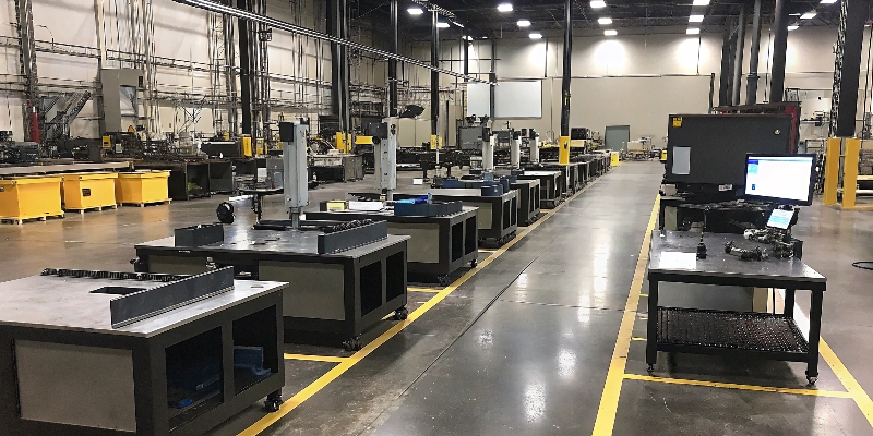
In my 20 years of developing die-cast parts, I’ve seen how quality is proven, not assumed. It’s built in the process and verified with data. For a Purchasing Director, seeing a supplier’s investment in top-tier inspection equipment is a direct indicator of their commitment to quality. For a Supplier Quality Engineer, it means he can rely on the data we provide, from the first PPAP samples to full-scale production. Let’s walk through the essential tools my team and I use every day to guarantee our parts meet the strictest standards.
How Does a Coordinate Measuring Machine (CMM) Ensure Dimensional Accuracy?
A part that is off by a fraction of a millimeter won’t fit during assembly. This simple error can halt an entire production line, causing massive delays and costing thousands in rework.
A CMM uses a high-precision probe to measure hundreds of points on a component. It verifies that all critical dimensions, geometric tolerances, and feature positions match the engineering drawing (CAD model) with micrometer-level accuracy, guaranteeing a perfect fit.
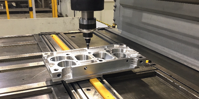
The CMM is the ultimate authority on dimensional truth. For every new project, especially complex automotive parts like the controller housings we produce, the CMM is the star of the First Article Inspection Report (FAIR) and PPAP. It’s not just about measuring length and width. We use it to verify complex GD&T callouts like flatness on a sealing surface, the true position of connector bores, and the perpendicularity of mounting faces. A client from Germany recently needed a new OBC housing with over 50 critical dimensions. Our CMM report gave their engineering team complete confidence that our tooling and process were perfectly aligned with their design intent before we even started mass production. It is a non-negotiable tool for precision manufacturing.
How Does an X-ray Inspection System Find Hidden Flaws?
A casting can look perfect on the outside but be riddled with internal voids. This hidden porosity compromises structural integrity and can lead to catastrophic failure or leaks under pressure, completely undetected by visual inspection.
An X-ray system shoots radiation through the casting, creating a 2D or 3D image of its internal structure. This allows inspectors to see and quantify the size and location of gas porosity or shrinkage voids, ensuring the part is solid and safe.
For any part that is safety-critical or must be perfectly airtight, X-ray inspection is not optional; it’s a requirement. I’ve worked on many steering and braking components where a single, critically located pore could lead to disaster. At EMP Tech, we use digital X-ray to inspect parts for our Tier 1 customers in the US and Europe. A key benefit of modern systems is the ability to automate defect recognition (ADR), where software helps identify and classify pores based on industry standards like ASTM. This removes human subjectivity and provides consistent, reliable data. For an EV motor housing, we X-ray the areas around bolt holes and sealing grooves to guarantee there are no hidden leak paths. This technology lets us see inside the metal, giving us and our customers total peace of mind.
What Makes an Optical 3D Scanner a Powerful Inspection Tool?
Inspecting complex, freeform surfaces with a CMM can be slow and may miss details between points. This leaves you with an incomplete picture of the part’s true shape, especially during initial prototyping and tool validation.
An optical 3D scanner projects a pattern of light onto the part and captures its entire surface geometry in millions of data points within seconds. This creates a detailed 3D color map that compares the actual part to the CAD model.
The 3D scanner has revolutionized how we do initial sample inspections. While a CMM is the king for final, critical dimension verification, the 3D scanner is the champion of speed and comprehensive surface analysis. When we get the first parts off a new tool, we can scan one in minutes and immediately get a color-coded deviation map. This map instantly shows us where the part is high, low, or perfectly matched to the design. Green means it’s perfect; warm colors (red, orange) mean excess material; cool colors (blue) mean not enough. This visual feedback allows my toolmakers to make precise adjustments to the mold much faster than relying on a long CMM report. It’s an incredibly powerful tool for accelerating the tool development and PPAP process.
How Do You Guarantee a Die Casting is Leak-Proof?
For housings containing electronics or fluids, a microscopic leak path is a catastrophic failure. Finding this leak after the component is fully assembled is incredibly expensive and damaging to your reputation for quality.
A leak testing machine seals the part and pressurizes it with air or a tracer gas like helium. Highly sensitive sensors then detect any pressure drop or escaping gas molecules, confirming the casting is perfectly airtight to a specific, measurable standard.
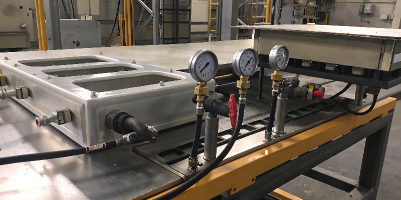
For the new energy vehicle parts we specialize in, like OBC and motor controller housings, leak testing is a 100% in-line production test. These parts must protect sensitive electronics from coolant and the outside environment for years. Air leak testing is the most common method. We submerge the pressurized part in water and look for bubbles or use a pressure decay sensor. For the most demanding applications, like those from our German automotive partners requiring extreme airtightness, we use helium mass spectrometry. Helium atoms are much smaller than air molecules and can find incredibly small leak paths. This test provides a quantifiable leak rate, ensuring every single part meets the customer’s strict specification before it ever leaves our factory. It’s the ultimate gatekeeper for airtight components.
Why is a Spectrometer the First Step in Quality Control?
Using the wrong aluminum alloy, or one with impurities, is a recipe for disaster. The parts may crack, corrode, or fail to meet mechanical strength requirements, undermining the entire production run.
A spectrometer analyzes the elemental composition of the raw material. It burns a small sample of the aluminum, reads the light spectrum it emits, and instantly provides a precise chemical breakdown, ensuring the alloy (e.g., ADC12) meets the exact specification.
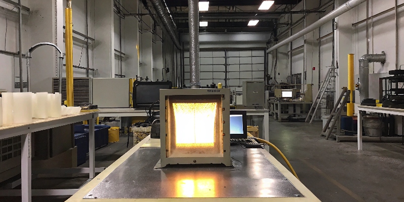
Quality starts with the raw material. Before a single ingot of aluminum is melted in our foundry, a sample is tested with our spectrometer. This is our first quality gate. It’s a simple, fast, and non-negotiable step. I tell my customers, the Purchasing Director, that this test protects them from the risks of material non-compliance. It confirms that the silicon content is correct for good castability, the copper is right for strength, and that harmful impurities like iron are below the maximum limit. We keep a record of the material certificate and our own spectrometer test for every single batch. This provides complete traceability and ensures that the foundation of every part we make is 100% correct and compliant with the customer’s drawing.
How Does a Surface Roughness Tester Prevent Seal Failures?
A surface that is too rough will tear a seal, and one that is too smooth may not allow the seal to grip properly. Incorrect surface texture on a critical sealing face is a primary cause of leaks.
A surface roughness tester, or profilometer, drags a fine diamond-tipped stylus across a surface. It measures the microscopic peaks and valleys to calculate a roughness value (like Ra), ensuring the finish is within the specified range for optimal sealing.
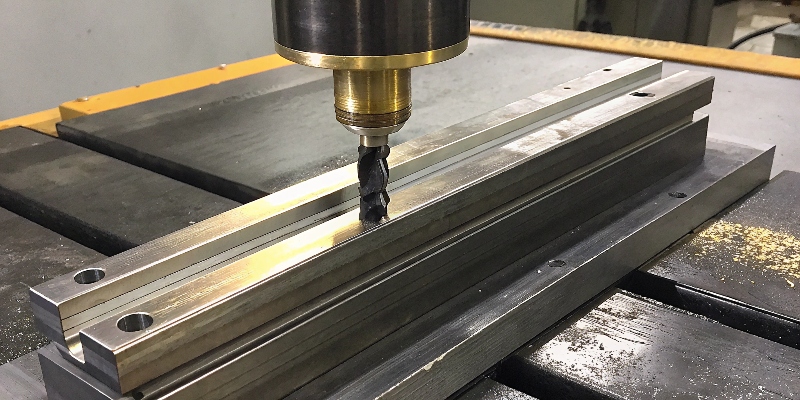
This is a perfect example of where a "good-looking" part can fail. A machined surface can look perfectly flat and shiny to the naked eye, but have the wrong texture at a microscopic level. I’ve seen this happen on oil pan and transmission housing projects. The engineering drawing will specify a roughness value (e.g., Ra 1.6-3.2 µm) for the gasket surface. We use our surface roughness tester to verify this during our process setup and for ongoing SPC checks. This data proves that our CNC machining process is stable and consistently producing the correct finish. For a quality engineer, having this data provides confidence that the part will perform reliably and form a perfect, leak-free seal in the final assembly.
When Do You Use an Ultrasonic Flaw Detector?
While X-ray is great for finding pores, it can struggle to detect flat, crack-like defects. Subsurface cracks or delaminations can be invisible to X-ray but represent a massive structural risk in the final part.
An ultrasonic flaw detector sends high-frequency sound waves into the part. The sound reflects off the back wall and any internal flaws. An operator can analyze the reflections to identify and locate subsurface cracks, porosity, or inclusions.
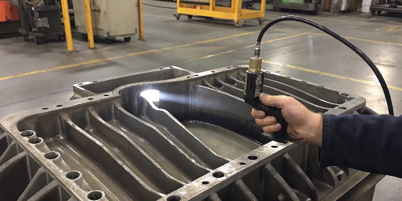
Think of ultrasonic testing (UT) as sonar for metal. It’s a highly effective non-destructive testing (NDT) method that complements X-ray. We often use it on thick-walled structural components where a high degree of internal integrity is required. For example, on a cast aluminum chassis component for a Canadian client, UT was specified to check for any internal discontinuities that could compromise strength in a crash event. The advantage of UT is its sensitivity to planar defects like cracks, which can be the most dangerous. While it requires a skilled operator to interpret the results correctly, it is an invaluable tool for ensuring the internal soundness of parts that simply cannot be allowed to fail. It provides another layer of safety and quality assurance.
How Does an Automated Vision System Improve Quality?
For high-volume production, having a human visually inspect every single part for surface defects is slow, expensive, and prone to error. Fatigue leads to missed flaws, resulting in quality escapes to the customer.
An automated vision inspection system uses one or more cameras, controlled lighting, and intelligent software. It automatically compares each part against a "golden sample" to instantly detect surface defects like porosity, cracks, flash, or missing features at high speed.
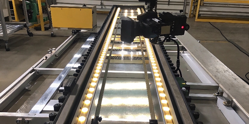
For projects that run in the tens or hundreds of thousands of parts per year, 100% manual inspection is not a sustainable quality strategy. This is where we implement automated vision systems. We worked on a small electronic connector housing where even a tiny bit of flash could prevent a proper connection. We set up a vision system right at the end of the production line. It inspects five critical areas on every single part in less than two seconds and automatically kicks out any non-conforming units. This technology provides objective, repeatable, and tireless inspection. For customers with high production volumes, it’s a powerful way to reduce defects, lower costs, and provide statistical data that proves the process is under control 24/7.
Why is a Microhardness Tester Important for Die Castings?
The mechanical properties of a casting are directly related to its hardness. A part that is too soft will fail under load. This is especially critical for alloys that are heat-treated to achieve specific strengths.
A microhardness tester presses a tiny, precisely shaped indenter (usually a diamond) into the part’s surface with a known force. By measuring the size of the indentation, it accurately determines the material’s hardness at a specific point.
Hardness is a quick and effective proxy for a part’s tensile strength. While a full tensile test pulls a sample apart, a hardness test is fast and minimally destructive. We use it to verify that our parts meet the mechanical properties required by the design. For example, some aluminum die castings undergo a T5 or T6 heat treatment to increase their strength. We use the microhardness tester to confirm that the heat treatment process was successful and that the entire batch has achieved the target hardness. We can test different areas of a part to check for uniformity. This test provides a quantitative data point that proves the part doesn’t just look right; it is fundamentally strong enough to do its job.
How Does a Salt Spray Chamber Validate Corrosion Resistance?
A part’s coating needs to protect it from corrosion for years in harsh environments. Promising durability is easy, but proving it requires simulating years of environmental exposure in a controlled, accelerated way.
A salt spray test chamber places coated parts in a heated, enclosed environment and exposes them to a continuous, fine mist of salt water. This accelerates corrosion, allowing us to evaluate the coating’s performance in hundreds of hours instead of years.
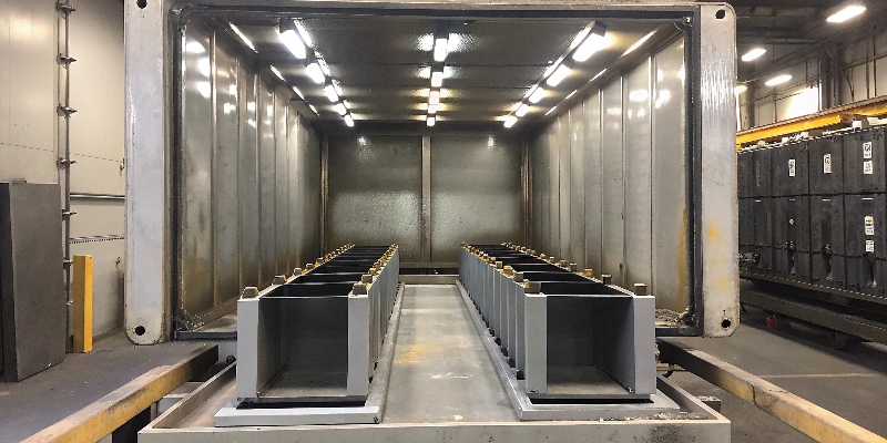
This is one of the most important validation tests we perform, especially for the automotive parts we ship globally. A vehicle operating through a German winter will be exposed to huge amounts of road salt. The salt spray test simulates this worst-case scenario. We will take sample parts that have been powder-coated or e-coated by our team and place them in the chamber for a specified duration, often 500 or 1,000 hours. Afterward, we inspect them for any signs of blistering, peeling, or red rust. Passing this test gives us and our customers the confidence that our surface treatment processes are robust and that the parts will remain protected and functional throughout their service life. It is objective proof of long-term durability.
Conclusion
The right inspection equipment is not a cost, but an investment in reliability. It provides the data to prove that every part meets its specifications from internal structure to surface finish.


