

A CAD model of an EV motor housing always looks flawless on a screen. The cooling channels are perfectly symmetrical, the walls are uniformly thin, and the O-ring grooves are sharply defined.
But when that 3D model hits the foundry floor and molten aluminum is injected at 5 meters per second, the reality of physics takes over. What looks like a brilliant design in software often turns into a nightmare of shrink porosity, thermal warpage, and coolant leaks during mass production.
Based on decades of evaluating aluminum die casting1 designs, here are five hidden design failures in EV motor housings that most engineers miss—and how to fix them before cutting steel.

1. Ignoring Draft Angles on Deep Cooling Jackets
EV motor housings require complex, integrated water jackets to dissipate the immense heat generated by the stator and power electronics. To maximize heat transfer, designers often draw extremely deep and straight cooling fins.
The Reality: If you do not apply adequate draft angles (tapers) to these deep cavities, the aluminum will shrink and grip the steel mold core tightly during solidification. When the ejector pins push the part out, it causes severe "galling" (dragging metal against metal) or even bends the housing.
The Fix: Incorporate a minimum draft angle of 1° to 1.5° on all deep internal cooling fins. If the thermal design cannot compromise on straight walls, you must consult your foundry to explore multi-piece slider mechanisms or optimized mold release sprays.
2. The "Machining Trap" Inside O-Ring Grooves
To achieve IP67/IP68 waterproof sealing, an EV Motor Controller Housing2 relies on a CNC-machined O-ring groove. Designers often place these grooves near the outer edges of the casting to save space.
The Reality: In High Pressure Die Casting (HPDC), the center of a thick wall is the last to cool, making it a natural gathering spot for micro-porosity (tiny internal voids). If your design requires CNC tools to cut the sealing groove right into the center of a thick flange, you expose that porosity. The result? The O-ring cannot seat perfectly against the rough, porous surface, and coolant will inevitably weep through.
The Fix: Work with a foundry that runs predictive Moldflow analysis. The solution is often to shift the sealing groove slightly, or utilize Vacuum HPDC to intentionally drive trapped gas into overflow wells away from the mating surface.
3. Designing Thin Walls Adjacent to Massive Bosses
Lightweighting is critical for EV range. Consequently, engineers try to make the main housing walls as thin as 1.5mm. However, they simultaneously attach massive, thick mounting bosses to secure the heavy inverter or transmission.
The Reality: The transition from a 1.5mm thin wall to a 15mm thick mounting boss creates a severe thermal gradient. The thin wall freezes instantly, cutting off the flow of molten metal to the thicker boss. The boss continues to shrink as it cools, but without fresh metal feeding it, severe shrink porosity and stress cracks develop at the junction.
The Fix: Gradual transitions are non-negotiable. Use generous radii (fillets) and hollow out thick bosses from underneath (using coring) to maintain a uniform wall thickness across the entire HPDC process3.
4. Unrealistic Coplanarity Expectations for Stator Mounts
The internal mounting pedestals for the stator and power modules must be perfectly flat. Many drawings demand strict coplanarity (e.g., 0.05mm) across multiple internal bosses, assuming the casting will naturally hold its shape.
The Reality: Aluminum castings inherently warp as they cool. If the CNC fixturing grips the part too tightly to machine these bosses, the part will spring out of tolerance the moment the clamps are released.
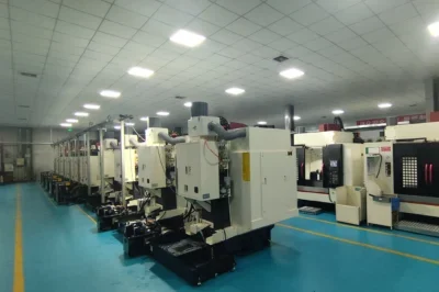
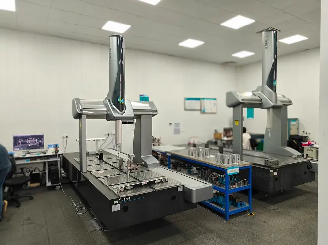
The Fix: Do not rely on the raw casting for strict geometric tolerances. Ensure your supplier utilizes single-setup 5-axis CNC machining with custom, low-distortion fixturing. This guarantees that all bearing bores and mounting pads are milled in one continuous operation, maintaining strict true position and coaxiality.
5. Overlooking Technical Cleanliness in Blind Tapped Holes
A mechanical design might be structurally sound, but blind holes (holes that do not go all the way through) for mounting bolts often become a hidden assembly killer in the EV sector.
The Reality: When blind holes are CNC machined and tapped for threads, aluminum chips and cutting fluids get trapped at the bottom. If these micro-debris are shaken loose during vehicle operation, they can easily cause a fatal short circuit on the high-voltage control board.
The Fix: Avoid blind holes whenever possible. If they are structurally necessary, specify strict Technical Cleanliness (VDA 19)4 standards. Your supplier must deploy intensive ultrasonic washing and vacuum drying systems to extract particles down to the micron level.
Catching Failures Before Cutting Steel
The most expensive mistake in automotive die casting is discovering a design flaw after the steel mold has been cut. Modifying a hardened steel tool can cause weeks of delays and cost thousands of dollars.
At EMP Tech, we bridge the gap between ideal CAD models and gritty manufacturing realities. Before any tooling begins, our engineers provide a ruthless, objective Design for Manufacturability (DFM) review. We analyze draft angles, identify porosity traps using Moldflow, and optimize CNC fixturing strategies.
Don’t let hidden flaws ruin your EV project.
Upload your 3D CAD today for a comprehensive DFM analysis and a pragmatic quote within 24 hours.
References & Footnotes
EMP Tech. Automotive Die Casting Solutions & Capabilities. ↩
EMP Tech. EV Motor Controller Housing Specifications. ↩
EMP Tech Blog. High Pressure Die Casting Explained: A Step-by-Step Process Guide. ↩
Verband der Automobilindustrie (VDA). VDA 19.1: Inspection of Technical Cleanliness. ↩


