OEM projects demand perfect parts, but casting defects1 create costly delays. You worry about high scrap rates2, missed deadlines, and quality issues that put your entire project at risk.
Optimizing OEM casting involves a systematic approach. It starts with early design analysis (DFM) and mold flow simulation, moves to precision process control on the factory floor, and is held together by strict quality standards and close supplier collaboration.

After more than 20 years in this industry, I have learned that "optimization" is not a single action. It is a continuous loop. You can have the best machine in the world, but if the part design is flawed, you will still make bad parts. True optimization connects every step, from the first CAD drawing to the final inspection report. My team and I have built our entire process around this idea. Let’s look at the key steps that make the biggest difference.
Why Is Early DFM (Design for Manufacturability) Analysis So Important?
A design looks great on the screen, but it is impossible to cast reliably. This common problem leads to endless engineering revisions, tooling changes, and expensive project delays.
DFM analysis connects the design engineer’s vision with the physical realities of die casting. It identifies potential problems like uneven wall thickness, insufficient draft angles, or areas prone to porosity before any metal is cut. This proactive step saves enormous time and money.

DFM is the first and most critical conversation between the product designer and the casting expert. In my experience, this is where we prevent 80% of future production headaches. A designer is focused on the part’s function, its weight, and how it fits into the larger assembly. My job is to look at that same design and figure out how molten aluminum will behave when we try to create it. We look for simple things that have a huge impact.
Finding and Fixing Problems Early
I remember a project for a new EV motor controller housing. The initial design had very deep, thin ribs for cooling. Functionally, it was great. But I knew from experience that the molten metal would cool too quickly trying to fill those ribs, leading to cold shuts and cracks. During our DFM review, my team suggested making the ribs slightly thicker and adding generous fillets at the base. This small change had no impact on the part’s thermal performance, but it completely solved the potential manufacturing defect.
Key DFM Checks for Castings
Our DFM checklist3 is long, but these are some of the most important points we review with every customer.
| DFM Check | Why It’s Important | Consequence of Ignoring It |
|---|---|---|
| Uniform Wall Thickness | Ensures even cooling and metal flow. | Porosity, warping, and sink marks. |
| Draft Angles | Allows the part to be ejected from the mold easily. | Scratches, drag marks, broken parts. |
| Fillets and Radii | Reduces stress concentration and improves metal flow. | Cracks, difficult mold filling. |
| Parting Line Location | Affects tooling cost, flash, and final part appearance. | Poor aesthetics, post-processing costs. |
How Does Mold Flow Simulation Predict and Prevent Defects?
You approve an expensive tool design, but the first parts off the line are full of hidden porosity. Now your project is behind schedule while you try to fix the mold.
Mold flow simulation is a virtual X-ray of the casting process. It shows exactly how the molten aluminum will fill, cool, and solidify inside the mold. This allows us to predict and prevent defects like air entrapment, cold shuts, and porosity before the tool is even built.
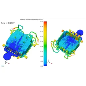
After the DFM stage, mold flow simulation is our most powerful tool. It’s like having a crystal ball for the casting process. Instead of guessing where the gates and overflows should go, we can test different configurations on a computer. This lets us fine-tune the mold design for optimal performance. I never recommend starting a new tool for a critical OEM part without a thorough simulation. The risk is just too high. We simulate the entire injection process, from the metal entering the cavity to the final solidification.
Virtual Prototyping Saves Real Money
We recently worked on a large structural part for an automotive client in Germany. The part had very high airtightness requirements. Our initial mold flow analysis showed a high probability of trapped gas porosity right in the middle of a critical sealing surface. If we had built the tool as originally designed, nearly every part would have failed the leak test. The simulation allowed us to redesign the runner and gating system to push the trapped air into an overflow area, away from the seal. We solved a million-dollar problem before spending a single dollar on steel.
Common Defects Predicted by Simulation
- Air Entrapment: Shows where pockets of gas will be trapped, causing porosity.
- Cold Shuts: Identifies areas where two fronts of molten metal meet but are too cool to fuse properly.
- Porosity: Predicts where shrinkage voids will form as the metal solidifies.
- Filling Pattern: Visualizes the complete flow of metal to ensure the cavity fills evenly.
Why Is Precision Mold Temperature Control So Crucial?
Your casting quality is inconsistent. One batch of parts is perfect, but the next has high scrap rates. You cannot figure out why, because the machine settings look the same.
The mold’s temperature directly controls how the aluminum cools. This determines the part’s final microstructure, dimensional accuracy, and mechanical properties. A stable, precisely controlled mold temperature is the key to producing consistent, high-quality parts shot after shot.

Many people focus only on the injection parameters of the die cast machine. But the mold itself is half of the process. I often tell my customers to think of the mold as a heat exchanger. We are injecting extremely hot metal into it, and we need to remove that heat in a very controlled and repeatable way. If one part of the mold is too hot and another is too cold, the part will warp and develop internal stresses. This is why we invest heavily in advanced mold temperature control systems.
Balancing Heat In and Heat Out
The goal is to maintain a thermal balance across the entire mold surface. To achieve this, we design complex cooling and heating channels directly into the mold steel. We use a mold temperature controller (TCU) to circulate oil or water at a specific temperature through these channels. For complex parts, especially those with both thick and thin sections, we might use multiple independent temperature control zones. This allows us to add heat to one area of the mold and aggressively cool another, ensuring the entire part solidifies at the ideal rate. This prevents defects and ensures the part meets its dimensional tolerances.
| Mold Temperature Issue | Resulting Defect | Solution |
|---|---|---|
| Too Cold | Cold shuts, flow lines, surface imperfections. | Increase TCU temperature, check for blocked channels. |
| Too Hot | Blisters, soldering (part sticks to mold), longer cycle time. | Decrease TCU temperature, improve cooling efficiency. |
| Uneven | Warping, porosity, dimensional instability. | Multi-zone control, redesign cooling channels. |
How Can Real-Time Process Monitoring Improve Casting?
A problem starts on the production line, but you only find it during quality inspection hours later. By then, you have already produced hundreds of bad parts that must be scrapped.
Real-time monitoring attaches sensors to the die cast machine and mold to track key variables for every single shot. The system instantly flags any deviation from the established process window, allowing operators to intervene immediately and preventing the mass production of defective parts.

In the past, we relied on periodic checks to control quality. We might inspect one part every hour. The problem is that a lot can go wrong in that hour. Today, for our OEM customers, this is not good enough. We use real-time monitoring systems that capture a complete digital fingerprint of every part we make. This data gives us incredible power to control the process and ensure stability. It is the foundation of a modern, data-driven factory.
From Reactive to Predictive Quality
This technology changes our entire approach to quality control. Instead of just finding bad parts, we can now predict when we are about to make them. For example, the system tracks the plunger’s velocity profile. We know from experience that if the velocity at a certain point drops by even a small amount, it can lead to flow marks on the final part. The real-time system can alert an operator or even stop the machine if it detects this trend. This allows us to fix the root cause—maybe a slight change in material temperature or a problem with hydraulics—before a single bad part is made. It’s about controlling the process, not just inspecting the product.
Key Parameters We Monitor:
- Injection Velocity Profile: The speed of the plunger at every stage.
- Pressures: Injection pressure, clamping pressure, and intensification pressure.
- Temperatures: Molten metal temp, mold surface temp (in multiple zones).
- Cycle Time: The exact time of each phase of the casting cycle.
How Do IATF 16949 and PPAP Standardize Quality Control?
Every supplier seems to have a different way of proving their quality. This makes it difficult for you to compare partners and trust that their processes are truly under control.
IATF 16949 is the global quality management standard for the automotive industry. PPAP (Production Part Approval Process) is the specific method used within that system to prove that a supplier can consistently produce parts that meet all of the customer’s engineering requirements.

For any supplier who wants to work with major OEMs, these are not optional. They are the rulebook we all must follow. IATF 16949 is the foundation—it defines how we must manage our entire organization to focus on quality, risk management, and continuous improvement. PPAP is the practical test. It is the comprehensive package of evidence we present to the customer before we are allowed to start mass production. My team and I live by these standards every day. They provide a common language for quality that our customers in Germany, the US, and Canada all understand and expect.
The Building Blocks of a Strong PPAP
Submitting a PPAP is the final exam of the development process. It forces us to prove, with data, that our process is stable and capable. It’s not just a stack of paperwork; it is the logical output of all the optimization steps we have already taken.
Key Elements of a PPAP Submission:
- Process FMEA (Failure Mode and Effects Analysis): Where we proactively identify everything that could possibly go wrong in our process and plan how to prevent it.
- Control Plan: The detailed recipe for making the part. It lists every process step, the specifications that must be met, and how we will measure and control them.
- Measurement System Analysis (MSA): A study that proves our measurement tools and methods are accurate and reliable.
- Process Capability Studies (Cpk): Statistical data from an initial production run that proves our process is capable of staying within the required engineering tolerances.
Why Is Close Collaboration Between OEMs and Suppliers Essential?
You send a detailed design to a supplier, but the parts that come back have issues. The long process of back-and-forth communication and revisions wastes valuable time and strains the relationship.
True collaboration turns a supplier into an expert partner. When OEMs and casting specialists work together from the very beginning, the supplier’s manufacturing knowledge can guide the design process. This partnership solves problems before they start, accelerates project timelines, and results in a better, more cost-effective part.

I cannot overstate the importance of this point. The best projects I have ever worked on were not the ones with the perfect initial design. They were the ones with the best communication and partnership. The "over-the-wall" approach—where an OEM designs a part and just throws it over to a supplier to make—simply does not work for complex modern components. Success requires a team effort. My most successful customers treat my engineering team as an extension of their own.
A Partnership That Delivers Results
I recall a recent project for an OBC housing. The customer involved us right after their initial concept design was finished. We had weekly meetings. They shared their CAD models, and we shared our DFM reports and mold flow simulation results. We made dozens of small adjustments together—moving a mounting boss here, adding a radius there. Because we were working so closely, we were able to finalize the design and order the tool much faster than usual. This collaborative process allowed us to launch production three months ahead of the original schedule. That is the power of a real partnership. It builds trust and delivers results that neither party could achieve alone.
Conclusion
Optimizing OEM casting is a continuous loop. It requires integrating early design analysis, simulation, precise process control, and a strong quality system, all powered by close, collaborative partnerships.


