

Let’s get one thing straight: choosing aluminum for an EV motor housing because it "has good thermal conductivity" is like choosing a CNC because it "makes chips." It’s table stakes. The real engineering battle isn’t about the material’s bulk thermal conductivity (k ≈ 150-180 W/m·K for common aluminum alloys). It’s about thermal resistance—and that resistance is defined by the casting process and the interface design.
We machine around 2,400 EV housings per day. The ones that keep their IGBTs and magnets in their happy temperature window aren’t just made of aluminum. They’re designed with casting defects in mind, and machined to minimize the interfaces that kill heat transfer.
The Casting Microstructure Effect on Heat Transfer
Here’s an inconvenient truth for the simulation crowd: your thermal FEA model assumes homogeneous material properties. The actual casting has porosity, silicon segregation, and oxide films. Each of those features is a thermal barrier.
The thermal conductivity of a die-cast AlSi10MnMg housing isn’t 150 W/m·K. It’s lower. How much lower depends on:
- Porosity distribution: Each pore is a void. Air has k ≈ 0.026 W/m·K. More pores = more insulation.
- Silicon morphology: Primary silicon particles don’t conduct heat as well as the aluminum matrix. The eutectic structure matters.
- Oxide entrainment: Folded oxides from turbulent fill are discontinuities in the thermal path.
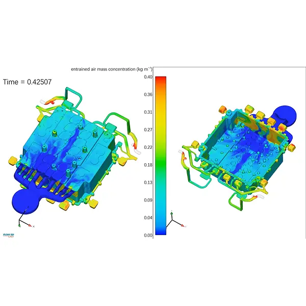
We run Moldflow simulations1 on every EV housing die not just to predict shrinkage—we use it to map the porosity risk zones. If a predicted porosity cluster sits under a power module mounting pad, we adjust the gate or overflow design to move it elsewhere. You can’t cast "zero porosity." You can cast "porosity where it won’t cause thermal or leak failures."
Machining: The Overlooked Thermal Interface
A casting leaves the die with an as-cast skin. That skin has a different microstructure than the bulk material—finer grain, less porosity, higher hardness. It’s actually the best thermal interface you have.
Then you machine it flat for the power module mount.
The moment you break through that skin, you expose the bulk material. If that bulk has localized microporosity, the heat transfer path from the IGBT to the coolant is compromised. The junction temperature drifts up. Efficiency drops.
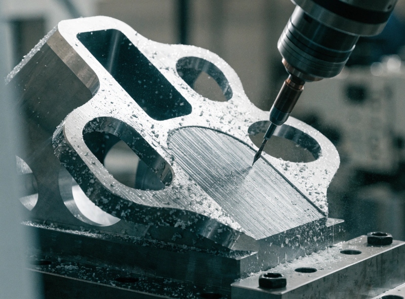
We handle this with single-setup machining on our 5-axis CNC centers. The critical mounting faces are finished in the same clamping cycle as the bore and the seal grooves. That ensures:
- Flatness of the mounting surface within 0.02 mm
- Surface finish at Ra 1.6 µm or better for thermal paste interfaces
- No re-clamping errors that create localized high spots (air gaps)
A high spot of 0.05 mm under a power module is a hot spot. Hot spots kill IGBTs.
Integrated Cooling Channels: Cast vs. Machined
The industry is moving to integrated water jackets cast directly into the housing. The alternative—drilled and plugged channels—adds interfaces, sealing risks, and cost.
Cast-in cooling channels are elegant but unforgiving. The wall thickness between the coolant and the electronics cavity might be 4 mm. If that 4 mm wall has a shrinkage pore, you have a coolant leak. Not "maybe." You have a leak.
Our approach:
- Design the water jacket with generous radii—sharp corners are casting defects waiting to happen
- Run thermal simulation on the die to ensure balanced cooling during solidification—uneven cooling creates hot spots and porosity
- 100% air-decay leak testing on every housing before it leaves the CNC line
The test protocol: 3 bar air pressure, 60-second dwell, decay rate < 0.5 cm³/min. That’s our internal spec. Most OEMs ask for 0.8. We run tighter because we’ve seen what a coolant leak does to a customer’s assembly line.
| Cooling Channel Type | Leak Risk | Thermal Performance | Manufacturing Cost |
|---|---|---|---|
| Cast-in (our process) | Low (with rigorous testing) | Excellent | Moderate |
| Drilled & plugged | Moderate (seal interfaces) | Good | High (secondary ops) |
| Sand-cast insert | Moderate (core integrity) | Excellent | High (core handling) |
Pin-Fin and Other Geometric Enablers
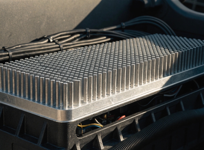
For high-power inverter housings, we regularly integrate pin-fin arrays into the casting design. These aren’t decorative. Each fin increases the surface area in contact with the coolant. More surface area = more heat extracted per unit volume.
The casting challenge is getting the molten aluminum to fill a dense array of thin, tall pins without cold shuts or incomplete fill. We use:
- High injection speed (4-6 m/s) to keep the metal fluid
- Die temperature control at 180-200°C to prevent premature solidification
- Vacuum assist (down to 50 mbar) to evacuate air from the pin cavities
A pin-fin array that’s 80% filled is useless. We don’t ship "mostly full."
Thermal Interface Materials (TIM): The Final Frontier
No matter how flat you machine the mounting pad, there’s still a microscopic gap between the power module and the housing. That gap is filled with thermal grease or a phase-change material.
We control the flatness and surface finish of the mounting pad to ensure the TIM layer is as thin as possible. A thinner TIM layer = lower thermal resistance. It’s physics.
Our typical spec for power module mounting pads:
- Flatness: 0.02 mm over the module footprint
- Surface finish: Ra 1.6 µm max (measured with Zeiss CMM equipment2)
- No step discontinuities from tool changes (eliminated by single-setup machining)
Practical Recommendations for Tier 1 Engineers
If you’re sourcing EV housings, here’s what we recommend you audit beyond the thermal conductivity spec:
- Porosity mapping on the mounting faces and cooling channel walls—not just bulk density
- Machining sequence—is the critical face machined first or last? Does the supplier use single-setup?
- Leak test correlation—air decay, helium, or water immersion? What’s the correlation to field performance?
- Surface finish capability—can they hold Ra 1.6 on the mounting face consistently across 20,000 parts?
Thermal management isn’t a material selection problem. It’s a manufacturing process control problem. And that’s where we do our best work.


