

Every DFM review starts with a customer PDF that has ±0.05mm called out on a raw as-cast dimension, and every time we have to walk that back before the kickoff meeting ends. Tolerance capability in HPDC isn’t a single number — it depends on whether the dimension is across the parting line, within a single die half, on a cored feature, or post-machined. Quoting one blanket tolerance for an entire drawing is how programs end up with disputed PPAP rejections six months into production.
This article breaks down what’s actually achievable in raw casting, what ISO 8062-3 CT grades mean in practice, and where 5-axis single-setup CNC machining is the only realistic path to tight tolerance — not the casting process itself.
As-Cast Tolerance: The Baseline Reality
For general dimensions on an aluminum HPDC part with no secondary machining, the industry reference is ISO 8062-3, which defines Casting Tolerance (CT) grades. High-pressure die casting typically falls into CT4 to CT6, depending on part size and geometry — not CT1 or CT2, regardless of what a customer’s legacy drawing says.
| Nominal Dimension Range | CT4 (mm) | CT6 (mm) | Typical As-Cast Achievable |
|---|---|---|---|
| Up to 25mm | ±0.14 | ±0.30 | ±0.10–0.15mm |
| 25–63mm | ±0.18 | ±0.40 | ±0.15–0.20mm |
| 63–160mm | ±0.22 | ±0.50 | ±0.20–0.30mm |
| 160–400mm | ±0.30 | ±0.70 | ±0.30–0.40mm |
| 400–1000mm | ±0.40 | ±1.00 | ±0.40–0.60mm |
These figures assume a stable tool, controlled die temperature, and single-cavity or well-balanced multi-cavity tooling. Add ±0.1–0.2mm on top of this table for any dimension that spans the parting line, since die-half alignment (tie-bar wear, platen parallelism) stacks directly into that measurement.
Why "One Tolerance Fits the Whole Part" Doesn’t Hold Up
1. Parting Line vs. Single-Die-Half Dimensions
A dimension measured entirely within one die half only inherits cavity machining accuracy and thermal shrinkage variation — typically the tighter end of the CT range. The moment a dimension crosses the parting line, it also inherits die-set alignment tolerance, clamping force deflection, and flash thickness variation. We flag parting-line-critical dimensions during DFM and, where the tolerance demands it, move that feature to a post-machined operation instead of holding it on the raw casting.
2. Cored Features vs. Direct-Formed Features
Deep cored holes (oil galleries, cooling channels) accumulate core deflection under injection pressure — expect an additional ±0.05–0.15mm per 50mm of core depth beyond a 3:1 depth-to-diameter ratio. This is a physical deflection under 600–1000 bar intensification pressure, not a tooling defect, and no amount of process tuning eliminates it below a certain depth ratio.
3. Shrinkage Variation Across Wall Thickness
Aluminum alloys (AlSi9Mn, AlSi10MnMg) shrink roughly 0.5–0.6% linearly on solidification, but that rate isn’t uniform across a part with mixed 2.5mm and 6mm wall sections — the thick section shrinks slightly more due to longer solidification time. On a 300mm datum span crossing both wall conditions, that differential alone can account for 0.15–0.25mm of dimensional spread before any tooling variation is added.
Where Tight Tolerance Actually Comes From: Post-Machining
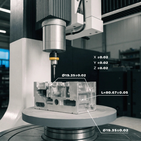
For any feature the customer specifies below CT4 as-cast capability — sealing bores, bearing seats, mounting faces for e-motor/inverter assembly — we don’t fight the casting process. We machine it.
| Feature Type | As-Cast Achievable | Post-CNC Achievable (Single-Setup 5-Axis) |
|---|---|---|
| Bearing bore diameter | ±0.15–0.25mm | ±0.010–0.020mm |
| Sealing face flatness | 0.15–0.30mm | 0.02–0.05mm |
| Bolt hole position (true position) | ±0.20–0.30mm | ±0.05mm |
| Bearing bore concentricity (2 bores, single part) | Not reliably controllable as-cast | ±0.015mm (single-setup eliminates re-fixture stack-up) |
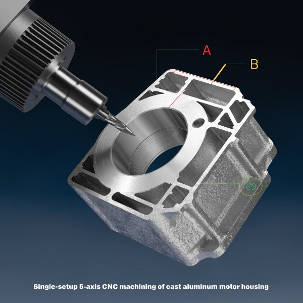
Single-setup 5-axis machining is the actual lever here, not the casting process itself. Once a raw casting is fixtured, every bore, face, and hole pattern referencing that datum gets machined without re-fixturing — which is where the concentricity and true-position numbers above come from. Quoting a machined tolerance without confirming single-setup capability on the fixture plan is how a "tight tolerance" spec quietly turns into two-operation machining with a stack-up error nobody accounted for.
GD&T Practice: What We Push Back On
Two recurring issues on incoming drawings:
- Datum structure not matched to the die’s parting line. If the GD&T datum scheme ignores where the die actually splits, you’re asking the casting process to hold a relationship it structurally can’t hold repeatably. We request datum realignment during DFM, not after first-article rejection.
- Bilateral tolerance applied to features with known shrinkage bias. Cored bore diameters shrink toward the core pin, not symmetrically — a bilateral ±0.15mm callout ignores that the actual distribution skews one direction. We recommend unilateral tolerancing on cored features based on historical Cpk data from the specific tool family, not a generic symmetric band.
Bottom Line
Realistic as-cast dimensional tolerance for aluminum HPDC sits in the CT4–CT6 range per ISO 8062-3, roughly ±0.10mm to ±0.60mm depending on nominal size, with an added allowance for any parting-line-crossing dimension. Anything tighter than that — bearing bores, sealing faces, bolt patterns for Tier 1 assembly interfaces — needs to be called out as a post-machined feature from the start, referenced to a single-setup 5-axis fixture plan. A tolerance spec that doesn’t distinguish between as-cast and machined features isn’t a tolerance spec a foundry can actually hold to; it’s a starting point for a DFM conversation.


